
Safety circuit arrangement and method for the fail-safe monitoring of a movement variable

a safety circuit and variable technology, applied in the direction of instruments, devices using electric/magnetic means, converting sensor output, etc., can solve the problems of inability to completely prevent the access to the danger area of an installation, and the permissibility of dangerous movement of the machine or installation, so as to achieve quick detection and check, the effect of reducing the effor

Active Publication Date: 2012-10-25
PILZ (COMPANY)
View PDF7 Cites 8 Cited by
  • Summary
  • Abstract
  • Description
  • Claims
  • Application Information

AI Technical Summary

Benefits of technology

[0013]The novel safety circuit arrangement, monitoring device and method are based on the idea of superposing a defined, individual reference signal on an encoder signal, which is supplied to the safety circuit arrangement at an input, preferably even before the actual signal evaluation. Advantageously, the reference signal is a DC voltage, i.e. the encoder signal has a DC voltage superposed on it. As a result, encoder signals having different signal levels can be processed and checked for plausibility. The encoder signal itself may have different signal levels which can be transformed to a desired level range by the reference signal. If the encoder signal is present without error, the superposition signal formed by the sum of the encoder signal and the reference signal has a particular signal level which, when measured, differs significantly from an erroneous encoder signal or from an absent encoder signal. The signal level which needs to be reached by the superposition signal differs significantly from the encoder signal alone, from an erroneous encoder signal and from the reference signal. As a result, the new safety circuit arrangement and the method allow safe recognition of an error in the connected encoder and an error during the signal transmission, e.g. owing to a cable fracture, and consequently generation of an error signal and intervention in the control of the machine part or possibly interruption of the movement of the machine part.
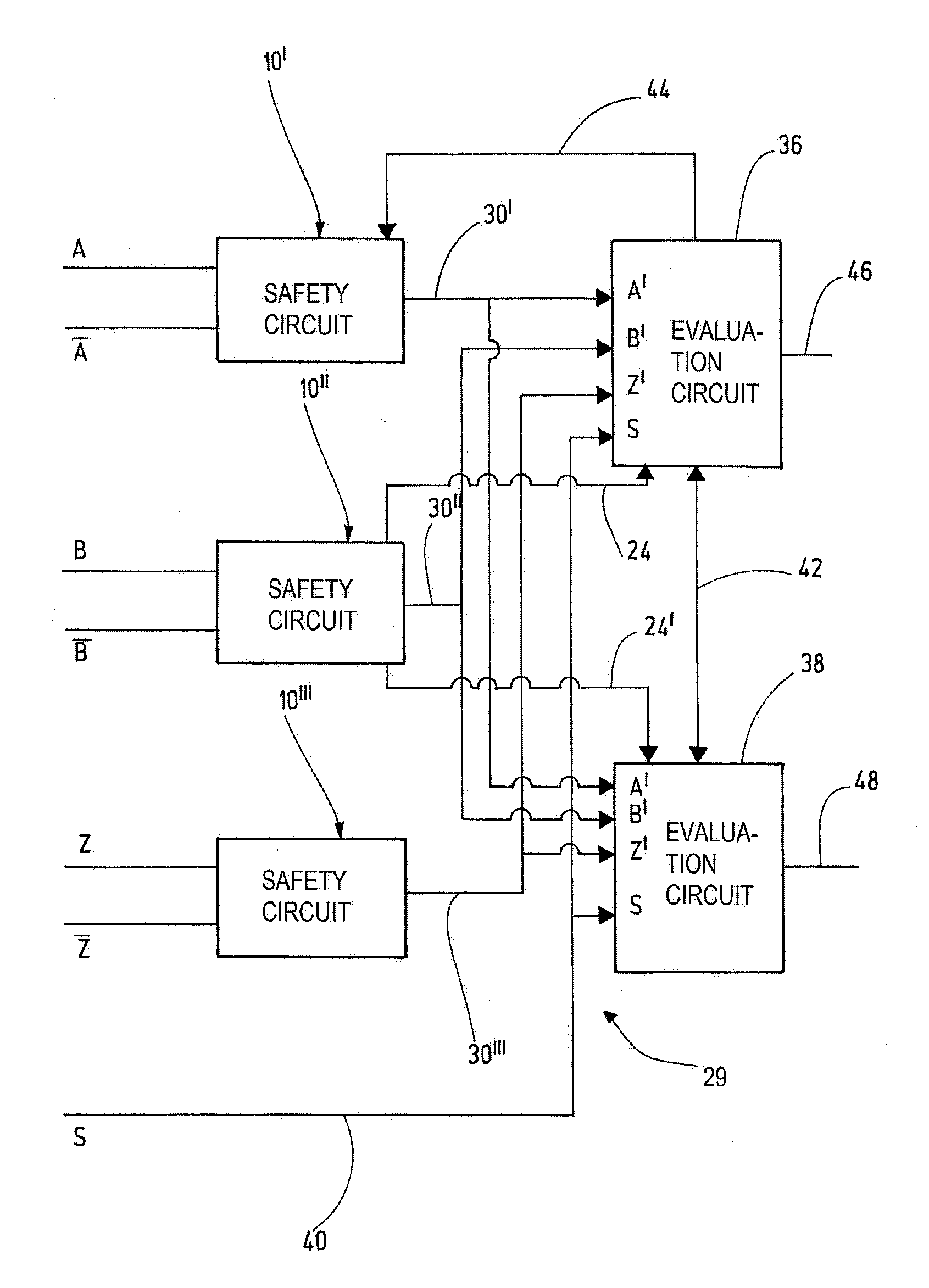
[0047]In this refinement, very reliable evaluation of the encoder signal is possible because a further redundant evaluation circuit is used. Hence, this redundancy contributes to increased failsafety of the novel safety circuit arrangement and of the novel method.

Problems solved by technology

However, there are cases in which access to a danger area of an installation cannot be entirely prevented, such as when setting up an automated operating sequence on a machine or an automatic door.
In this case, the dangerous movement of the machine or installation is permitted only when and for as long as the redundant measurement results for the dangerous movement variable correspond.

Method used


Image

  • Safety circuit arrangement and method for the fail-safe monitoring of a movement variable
  • Safety circuit arrangement and method for the fail-safe monitoring of a movement variable
  • Safety circuit arrangement and method for the fail-safe monitoring of a movement variable

Examples


Embodiment Construction

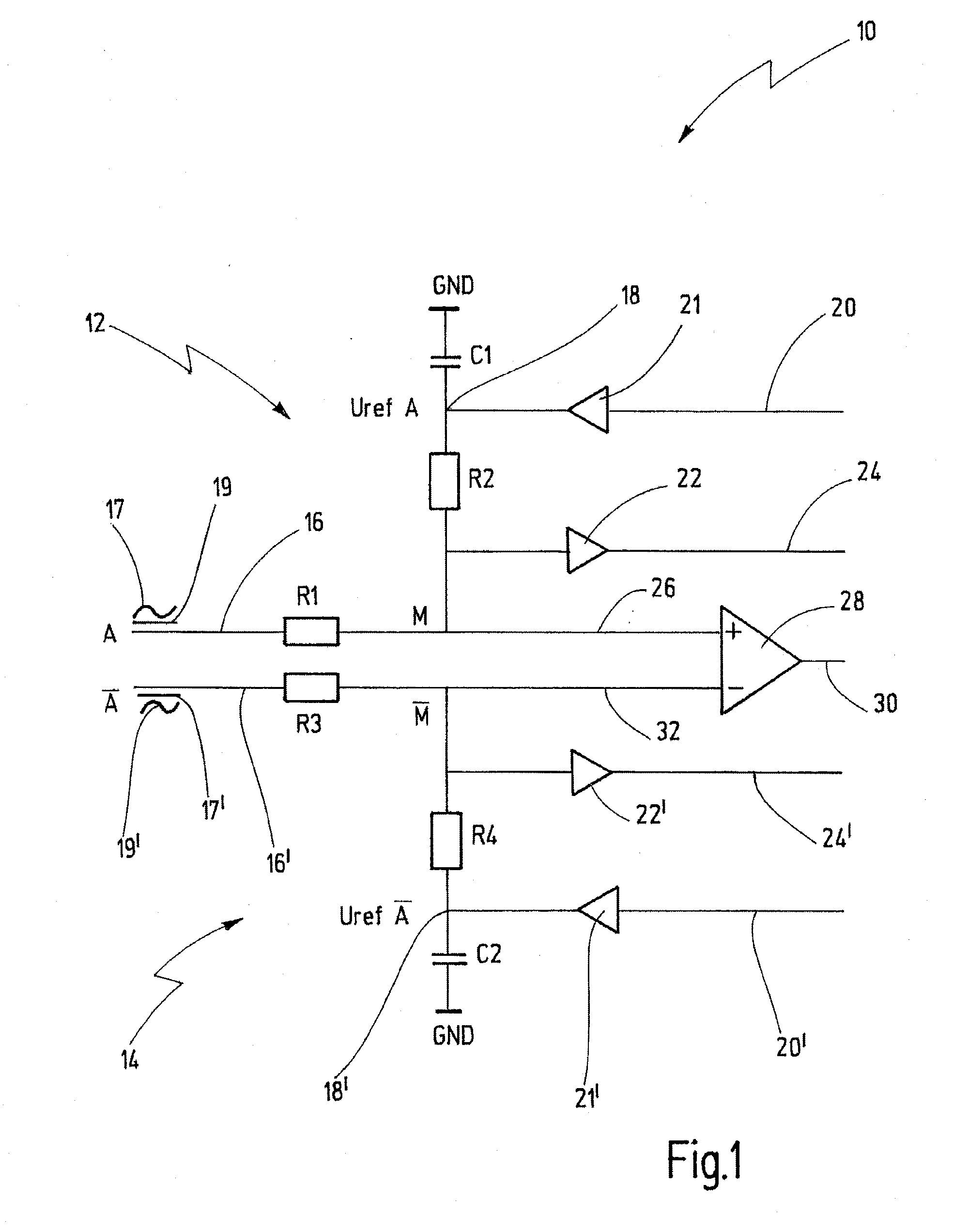
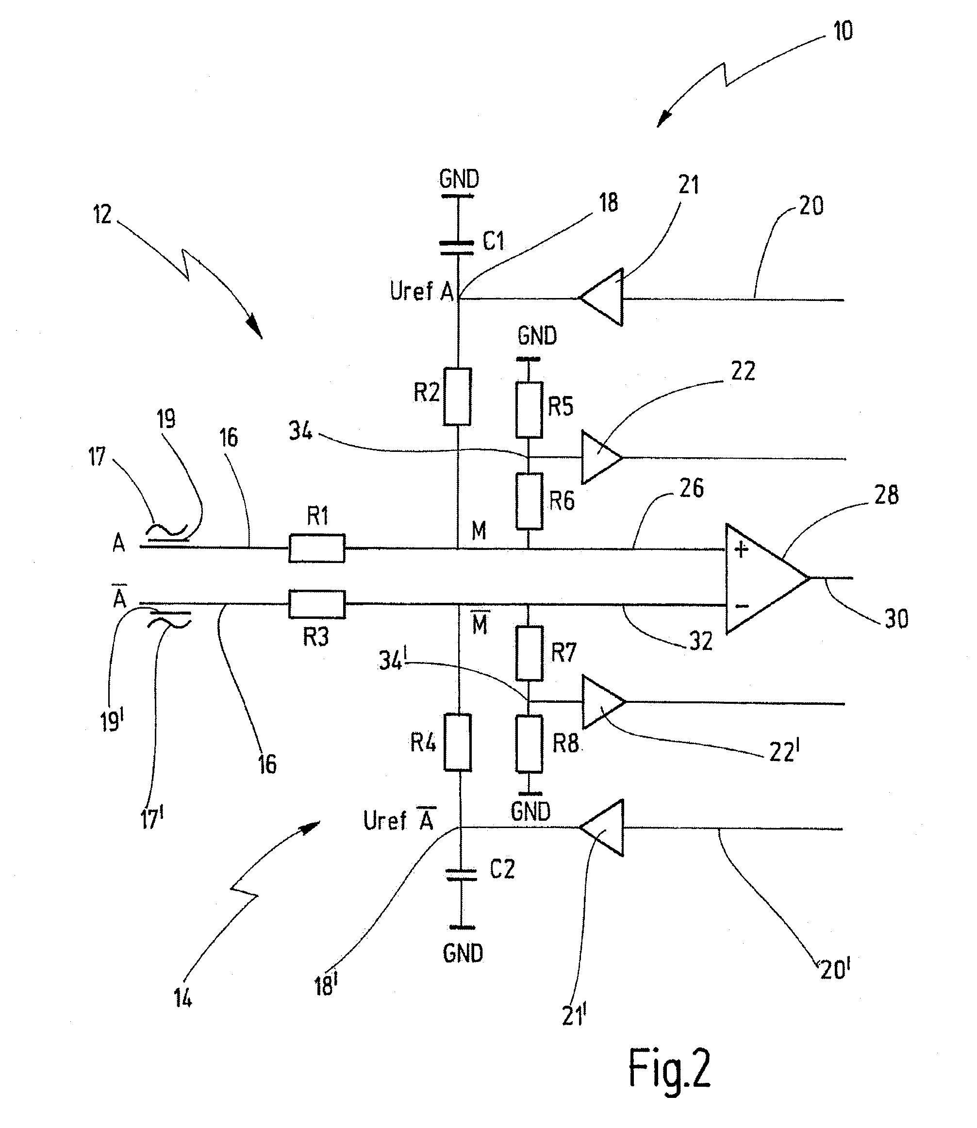
[0054]In FIG. 1, a safety circuit arrangement is denoted by the reference numeral 10 in its entirety.

[0055]The safety circuit arrangement 10 has a first safety circuit 12 and a second safety circuit 14. In this preferred case, the safety circuits 12, 14 are of identical design. The safety circuit 12 has an input signal line 16 which is used to supply an encoder signal A to the safety circuit 12. The encoder signal A preferably has an AC signal component 17 which is representative of a movement, for example a rotational movement of a shaft. However, the encoder signal A may also merely have a DC component 19, the level of which is representative of the movement, for example. The encoder signal A may also be a mixed signal comprising an AC signal component 17 and a DC component 19. In any case, the input signal line 16 is here connected to a tap M via a resistor R1. The tap M is connected to a reference voltage point 18 via a resistor R2. The reference voltage point 18 has a reference...


PUM


Abstract

A safety circuit arrangement for the failsafe monitoring of a movement variable of a moving machine part has a signal input for supplying an encoder signal, with the encoder signal being representative of the movement variable to be monitored. The arrangement also has a reference signal path for supplying a reference signal, a tap connected to the signal input and to the reference signal path in order to provide a superposition signal by superposing the reference signal on the encoder signal, and a measuring unit which is connected to the tap and is designed to detect whether the superposition signal reaches at least one predefined signal level or is within a predefined signal level range.

Description

CROSS-REFERENCES TO RELATED APPLICATIONS[0001]This application is a continuation of international patent application PCT / EP2010 / 068021 filed on Nov. 23, 2010 designating the U.S., which international, patent application has been published in German language and claims priority from German patent applications DE 10 2009 055 991.4 filed on Nov. 23, 2009 and DE 10 2009 057 196.5 filed on Nov. 30, 2009. The entire contents of these priority applications are incorporated herein by reference.BACKGROUND OF THE INVENTION[0002]The present invention relates to a safety circuit arrangement, a monitoring device comprising a plurality of such safety circuit arrangements and a method for the failsafe monitoring of a movement variable of a moving machine part, in particular for the failsafe monitoring of a rotational speed and / or a rotational position.[0003]The invention particularly relates to the failsafe evaluation of a rotational speed sensor for the protection of a danger area on an automatic...

Claims


Application Information

Patent Timeline
IPC IPC(8): G01P3/56
CPCG05B9/02G01D5/24461H02H7/0844
Inventor LATURNER, ANDRE
Owner PILZ (COMPANY)
Learn More