Low voltage isolation switch, in particular for a transmission channel for ultrasound applications

a low-voltage isolation switch and transmission channel technology, applied in the direction of electric variable regulation, automatic control of pulses, instruments, etc., can solve the problems of partial reflection and total reflection of ultrasounds

Active Publication Date: 2012-10-25
STMICROELECTRONICS SRL
View PDF1 Cites 12 Cited by
  • Summary
  • Abstract
  • Description
  • Claims
  • Application Information

AI Technical Summary

Benefits of technology

[0035]One embodiment of the present disclosure is a switching circuit able to avoid undesired mitigations of a signal at its input during the receiving step, ensuring a correct working of a transmission channel that includes the switching circuit between

Problems solved by technology

It is to be noted that, the big impedance difference between a bone and a tissue being considered, with the sonography it is not possible to see beh

Method used


Image

  • Low voltage isolation switch, in particular for a transmission channel for ultrasound applications
  • Low voltage isolation switch, in particular for a transmission channel for ultrasound applications
  • Low voltage isolation switch, in particular for a transmission channel for ultrasound applications

Examples


Embodiment Construction

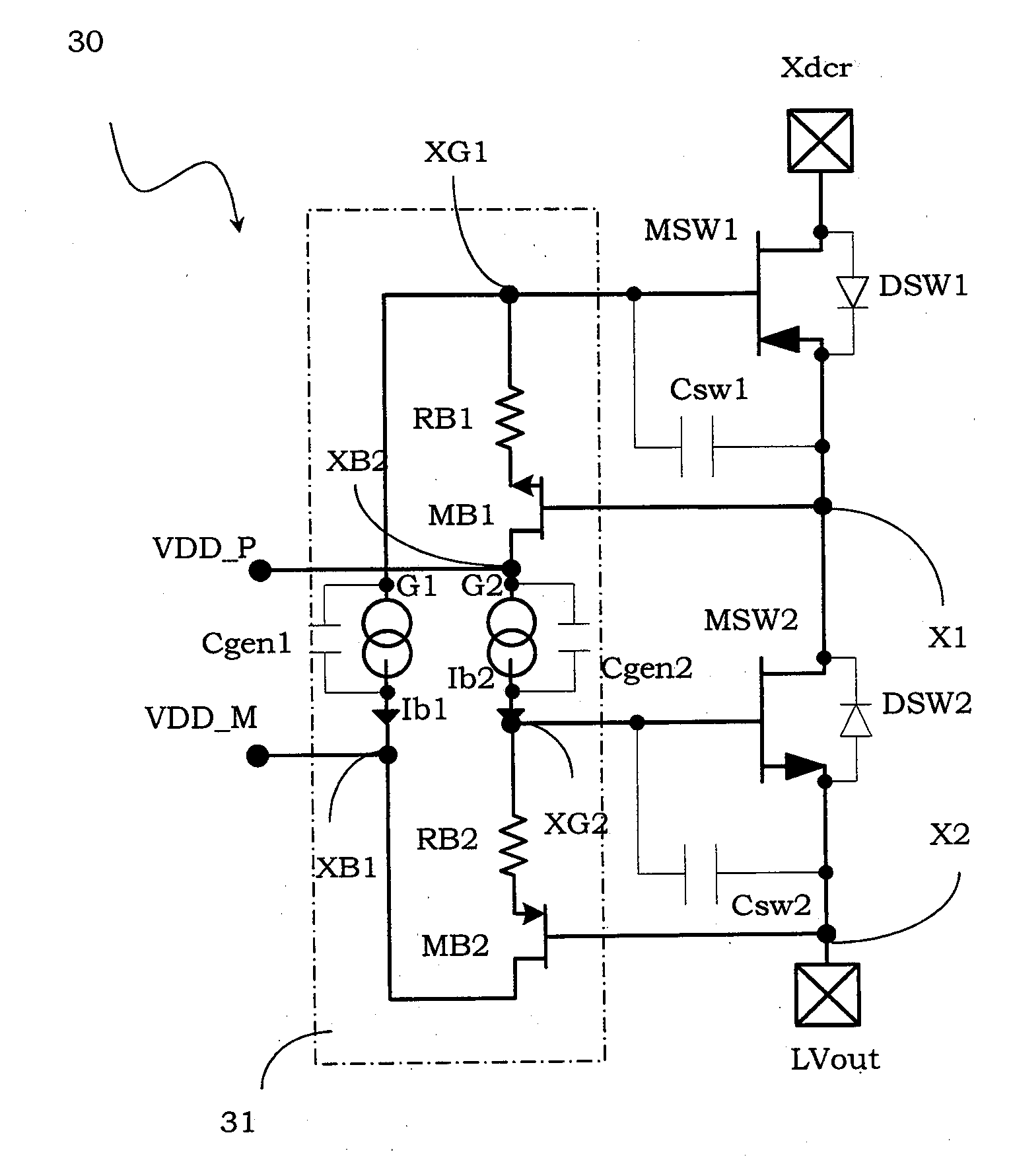
[0055]With reference to these figures, and in particular to FIG. 3A, a switching circuit 30 is described, in particular that can be used in the transmission channel 1 of FIG. 1 instead of the switching circuit 7, such as for ultrasound applications.

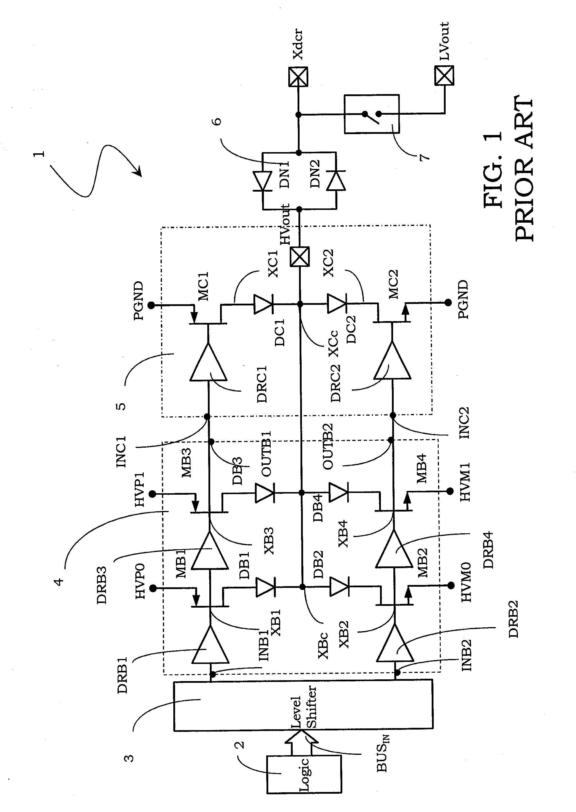
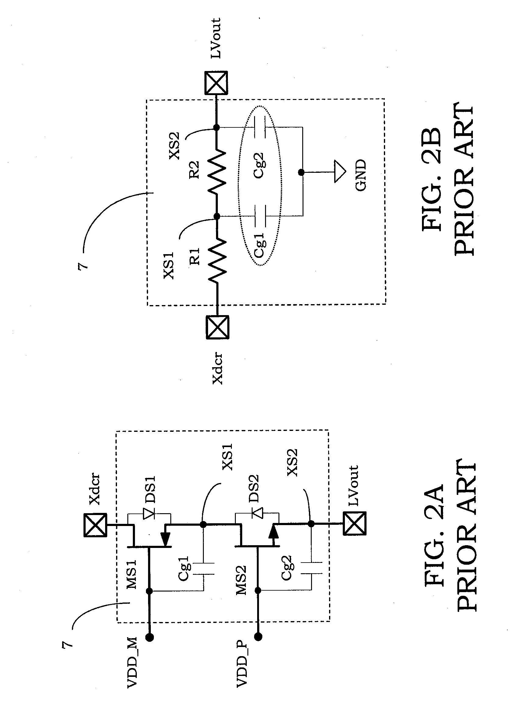
[0056]Elements that structurally and functionally correspond to the high voltage switch 7 of the transmission channel described in relation to the prior art and shown in FIGS. 1 and 2A will be given the same alphanumeric references for simplicity of illustration.

[0057]The switching circuit 30 comprises at least one first switching transistor MSW1 and one second switching transistor MSW2 electrically coupled in series to each other between the connection terminal Xdcr and the output terminal LVout of a transmission channel 1 shown in FIG. 1 and described with reference to the prior art. In particular, the switching circuit 30 is suitable for being used as switching circuit between a receiving mode and a transmission mode of this transmissi...


PUM


Abstract

A switching circuit is electrically coupled between a connection terminal and an output terminal of a transmission channel and includes first and second switching transistors electrically coupled in series to each other and having respective body diodes in anti-series, between the connection terminal and the output terminal. The switching circuit comprises a bootstrap circuit connected to respective first and second control terminals of these first and one second switching transistors, as well as to respective first and second voltage references. The bootstrap circuit includes a first parasitic capacitance electrically coupled between the first control terminal and a first bootstrap node, and a second parasitic capacitance electrically coupled between the second control terminal and a second bootstrap node. The parasitic capacitances have value of at least one order of magnitude lower with respect to the gate-source capacitances of the first and second switching transistors.

Description

BACKGROUND[0001]1. Technical Field[0002]The present disclosure relates to a switching circuit. More specifically the disclosure relates to a switching circuit electrically coupled between a connection terminal and an output terminal of a transmission channel and comprising at least one first and one second switching transistor electrically coupled in series to each other between the connection terminal and the output terminal. The disclosure also relates to a transmission channel comprising at least such a switching circuit. The disclosure particularly, but not exclusively, relates to a switching circuit configured to switch between a receiving mode and a transmission mode and suitable for being used by a transmission channel for ultrasound applications and the following description is made with reference to this field of application by way of illustration only.[0003]2. Description of the Related Art[0004]As is well known, sonography or ultrasonography is a system of medical diagnos...

Claims


Application Information

Patent Timeline
IPC IPC(8): H03K17/687H03L5/00
CPCH03K19/018521G05F3/02H03K19/09443
Inventor ROSSI, SANDRORICCIARDO, ANTONIOGHISU, DAVIDE UGO
Owner STMICROELECTRONICS SRL
Why Eureka
Try Eureka