Image capture apparatus

a technology of image capture and apparatus, applied in the field of image sensors, can solve the problems of high power consumption and inability to turn on and off the power supply of the readout circuit, and achieve the effect of suppressing an increase in power consumption and increasing the speed of reading out pixel signals

Inactive Publication Date: 2012-10-25
CANON KK
View PDF6 Cites 9 Cited by
  • Summary
  • Abstract
  • Description
  • Claims
  • Application Information

AI Technical Summary

Benefits of technology

[0007]The present invention has been made in consideration of the above problems, and suppresses an

Problems solved by technology

According to the conventional technique disclosed in Japanese Patent Laid-Open No. 08-111821 described above, however, since the number of readout circuits increases, the power consumption is high even at the t

Method used


Image

  • Image capture apparatus
  • Image capture apparatus
  • Image capture apparatus

Examples


first embodiment

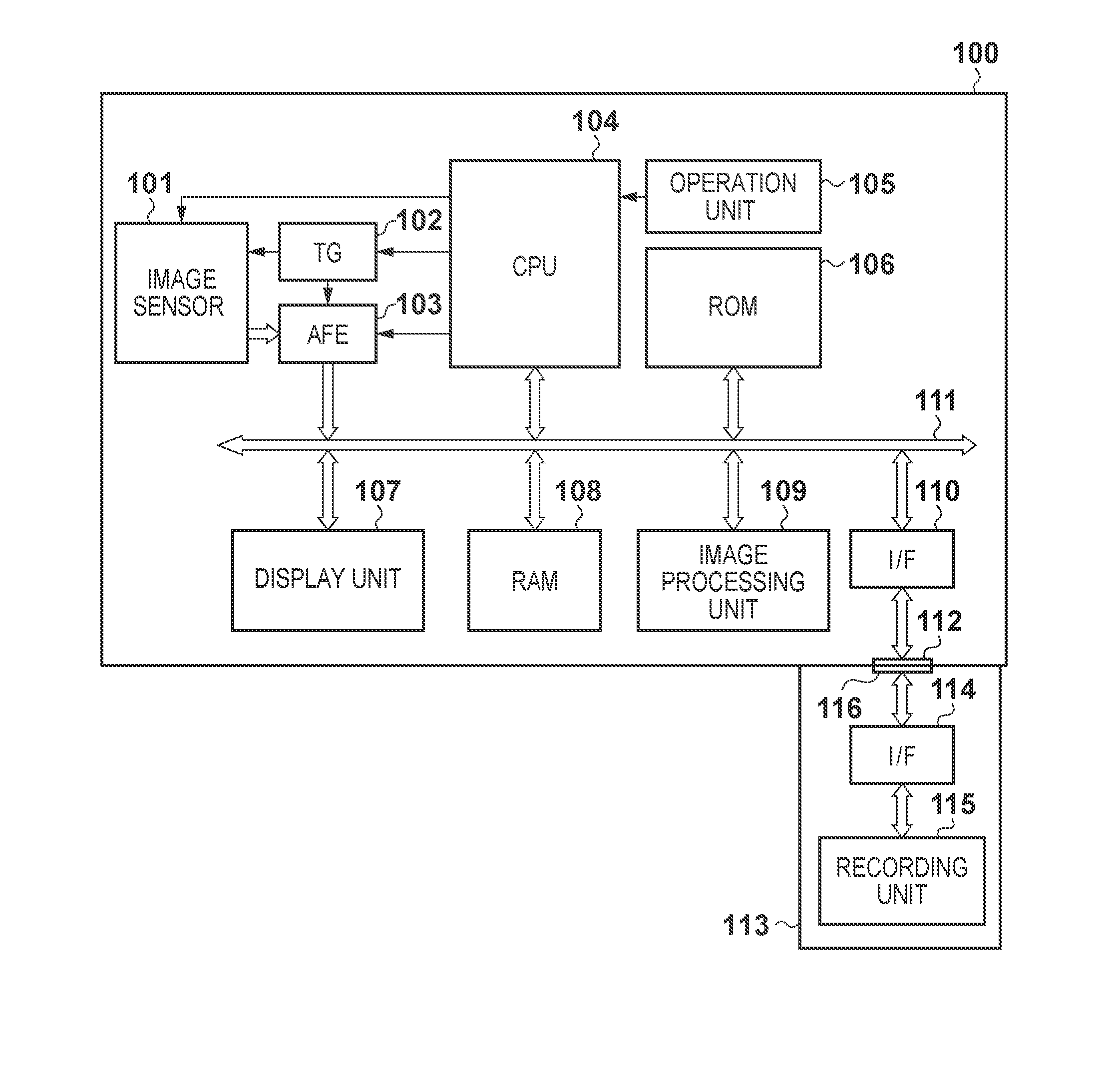
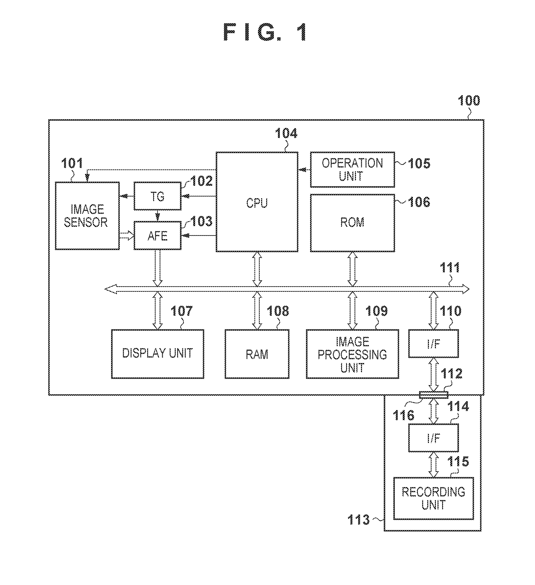
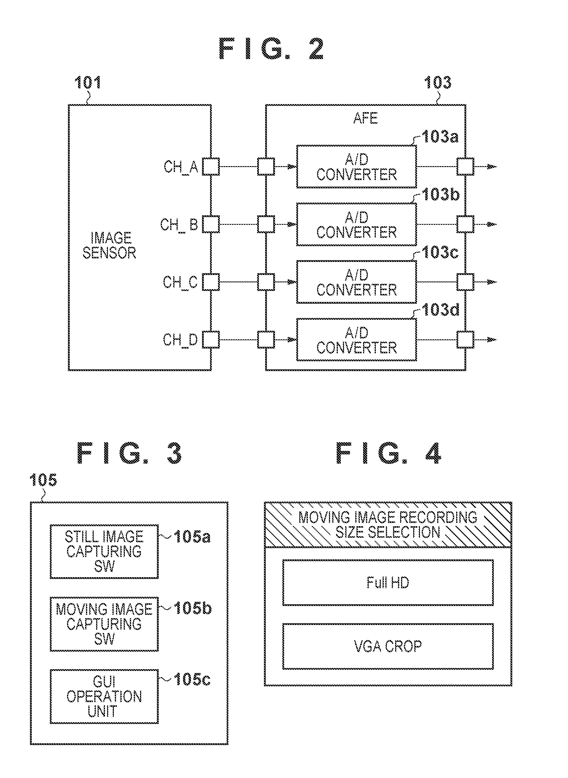
[0029]FIG. 1 is a block diagram showing the arrangement of an image capture apparatus common to the respective embodiments of the present invention. In an image capture apparatus 100 shown in FIG. 1, an image sensor 101 has pixels two-dimensionally arrayed, and photoelectrically converts an object image. An analog front end (to be referred to as an AFE hereinafter) 103 digitally converts the analog image signal output from the image sensor 101 in accordance with gain adjustment and a predetermined quantization bit. A timing generator (to be referred to as a TG hereinafter) 102 controls the driving timings for the image sensor 101 and the AFE 103. As shown in FIG. 2, the AFE 103 includes A / D converters 103a to 103d corresponding to the output channels of the image sensor 101. It is possible to independently ON / OFF-control the A / D converters 103a to 103d in accordance with settings from a CPU 104 (to be described later).

[0030]A RAM 108 has both the function of a image data storage uni...

second embodiment

[0101]The operation of an image capture apparatus according to the second embodiment of the present invention will be described below. Since the arrangement of the image capture apparatus according to this embodiment is the same as that of the image capture apparatus according to the first embodiment, a description of the arrangement will be omitted. The image capture apparatus according to the second embodiment has the same image capturing modes as those described in the first embodiment. An image sensor 101 operates by using different driving methods in the respective image capturing modes.

[0102]Prior to a description of the operation of the image sensor 101 in each image capturing mode, the arrangement of the image sensor 101 in this embodiment will be described with reference to FIG. 13. Referring to FIG. 13, an effective pixel region of the image sensor is formed by pixel sets 312a, 312b, 312e, and 312f arranged in the vertical direction. In addition, pixel sets 312c, 312d, 312...


PUM


Abstract

An image capture apparatus includes an image sensor, a determination unit which determines one image capturing mode, a driving unit which drives the image sensor by different driving methods in the respective image capturing modes, and a control unit which controls the operation of the driving unit. The image sensor includes a plurality of two-dimensionally arrayed pixels, a predetermined number of vertical output lines arranged for each array of pixels, and a holding memory which holds pixel signals from pixels on rows. The control unit drives the image sensor in the first power save mode when a horizontal transfer period is not less than twice a vertical transfer period, and drives the image sensor in the second power save mode when the vertical transfer period is not less than twice the horizontal transfer period.

Description

BACKGROUND OF THE INVENTION[0001]1. Field of the Invention[0002]The present invention relates to an image sensor including a plurality of pixels arranged in a matrix in the horizontal and vertical directions and an image capture apparatus and, more particularly, to an image sensor having a plurality of driving methods and an image capture apparatus.[0003]2. Description of the Related Art[0004]Recently, with an increase in the number of pixels of an image sensor, it is necessary to read out pixel signals at high speed to ensure a frame rate or the like.[0005]For example, Japanese Patent Laid-Open No. 08-111821 has proposed a technique of increasing a frame rate by providing a plurality of vertical signal lines for one pixel column and simultaneously performing vertical / horizontal transfer for two rows.[0006]According to the conventional technique disclosed in Japanese Patent Laid-Open No. 08-111821 described above, however, since the number of readout circuits increases, the power co...

Claims


Application Information

Patent Timeline
IPC IPC(8): H04N5/335
CPCH04N5/343H04N5/3454H04N5/378H04N5/347H04N5/3742H04N5/3456H04N25/42H04N25/443H04N25/445H04N25/46H04N25/767H04N25/75
Inventor SAMBONSUGI, HIDEAKI
Owner CANON KK
Why Eureka
Try Eureka