
Spoiler

a technology of spoiler and spoiler body, which is applied in the field of spoiler of automobiles, can solve the problems of increasing the number of processes, raising the risk of damaging the antenna, adversely affecting the external appearance of the spoiler, and risk of damaging the electronic device component, so as to improve the bonding strength of the vibration-welded structure

Inactive Publication Date: 2012-11-01
INOAC CORP
View PDF23 Cites 10 Cited by
  • Summary
  • Abstract
  • Description
  • Claims
  • Application Information

AI Technical Summary

Benefits of technology

[0008]Illustrative aspects of the present invention provide a spoiler in which a bonding strength in a vibration-welded structure is improved without adversely affecting an external appearance of the spoiler.

Problems solved by technology

However, to arrange an antenna inside a blow-molded spoiler, a hole is bored in the spoiler, which increases the number of processes and raises a risk of damaging the antenna.
While this defect may be remedied by thickening the ribs 40 to provide robustness, this may in turn cause a sink mark on a surface of the spoiler due to the welding on the thickened ribs, thereby adversely affecting an external appearance of the spoiler.
Further, when a related art two-piece spoiler is configured to accommodate an electronic device component, such as an AM / FM radio broadcast antenna and a digital TV broadcast antenna, vibration welding is carried out with the electronic device component arranged inside the spoiler, and therefore, there may still be a risk of damaging the electronic device component.
While the spoiler may be configured to provide a sufficient space such that the electronic device component is not hit during the vibration welding, this results in an increase in size of the spoiler accordingly.
Even if a sufficient space can be provided such that the electronic device component is not hit during the vibration welding, there arises a problem that the electronic device component may resonate with a vibration while the vehicle is moving, in which case the electronic device component may generate a noise or performance degradation due to its vibration.

Method used


Image

  • Spoiler
  • Spoiler
  • Spoiler

Examples


Embodiment Construction

[0026]Hereinafter, an exemplary embodiment of the present invention will be described in detail with reference to the drawings.

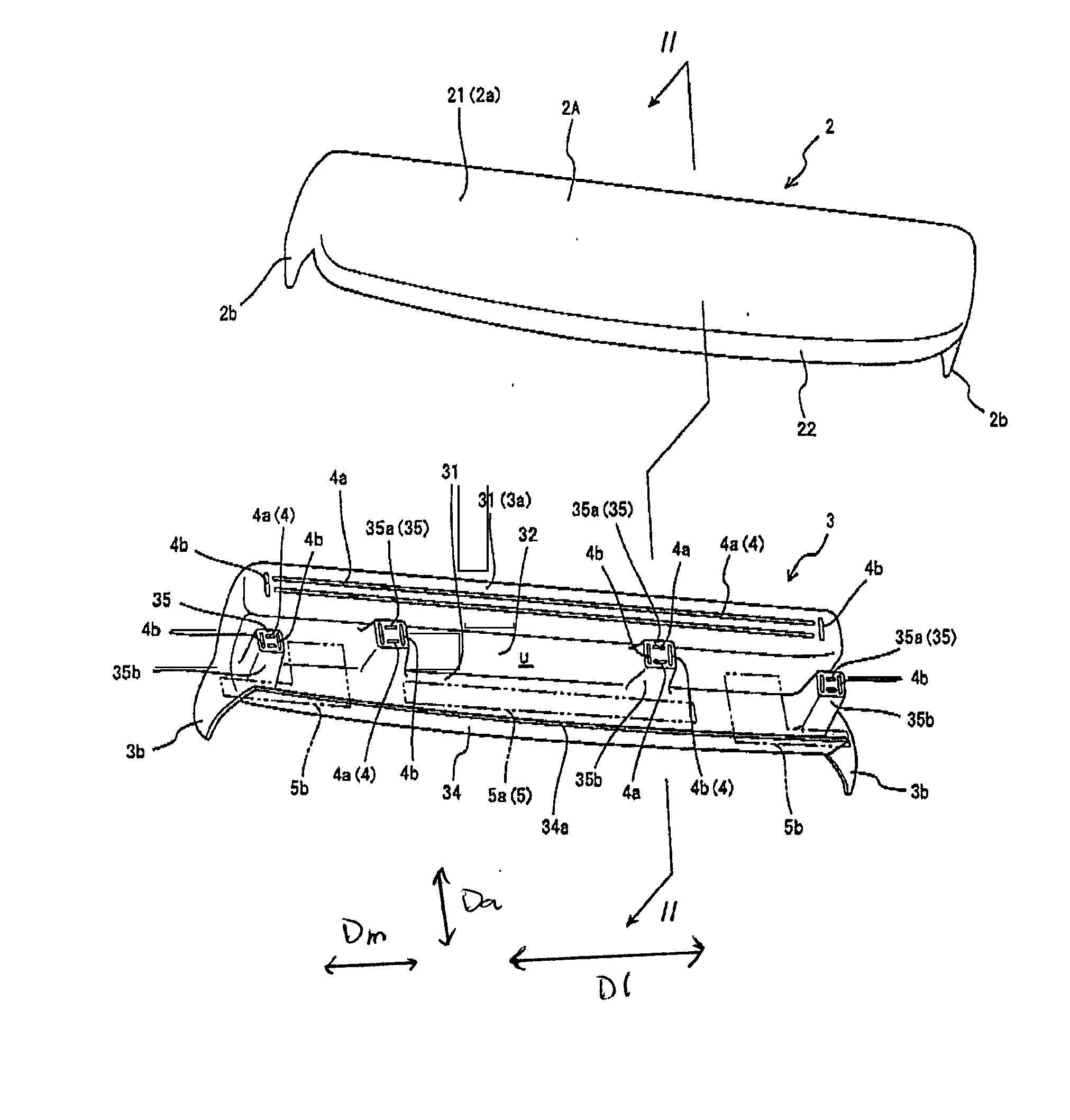
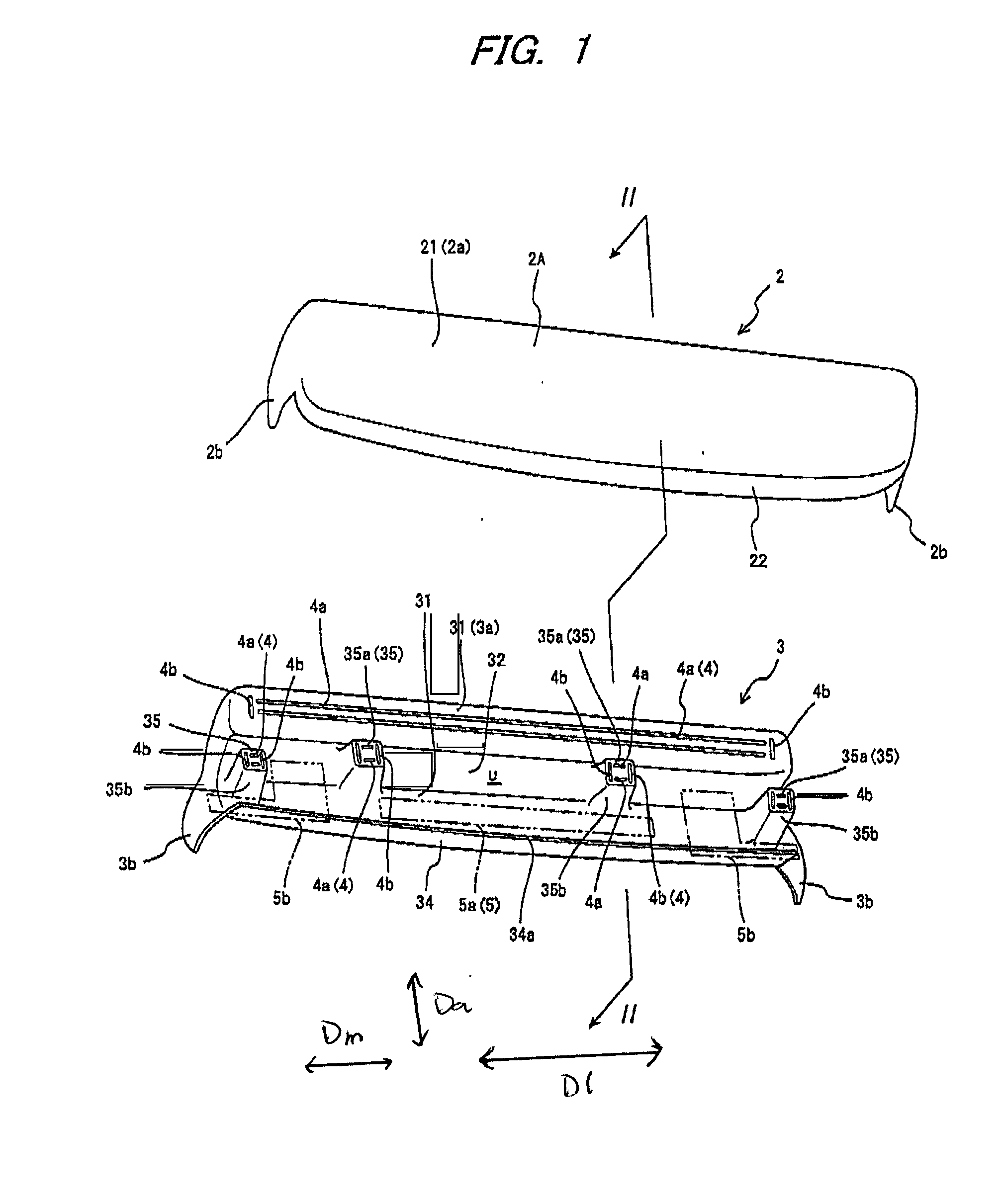
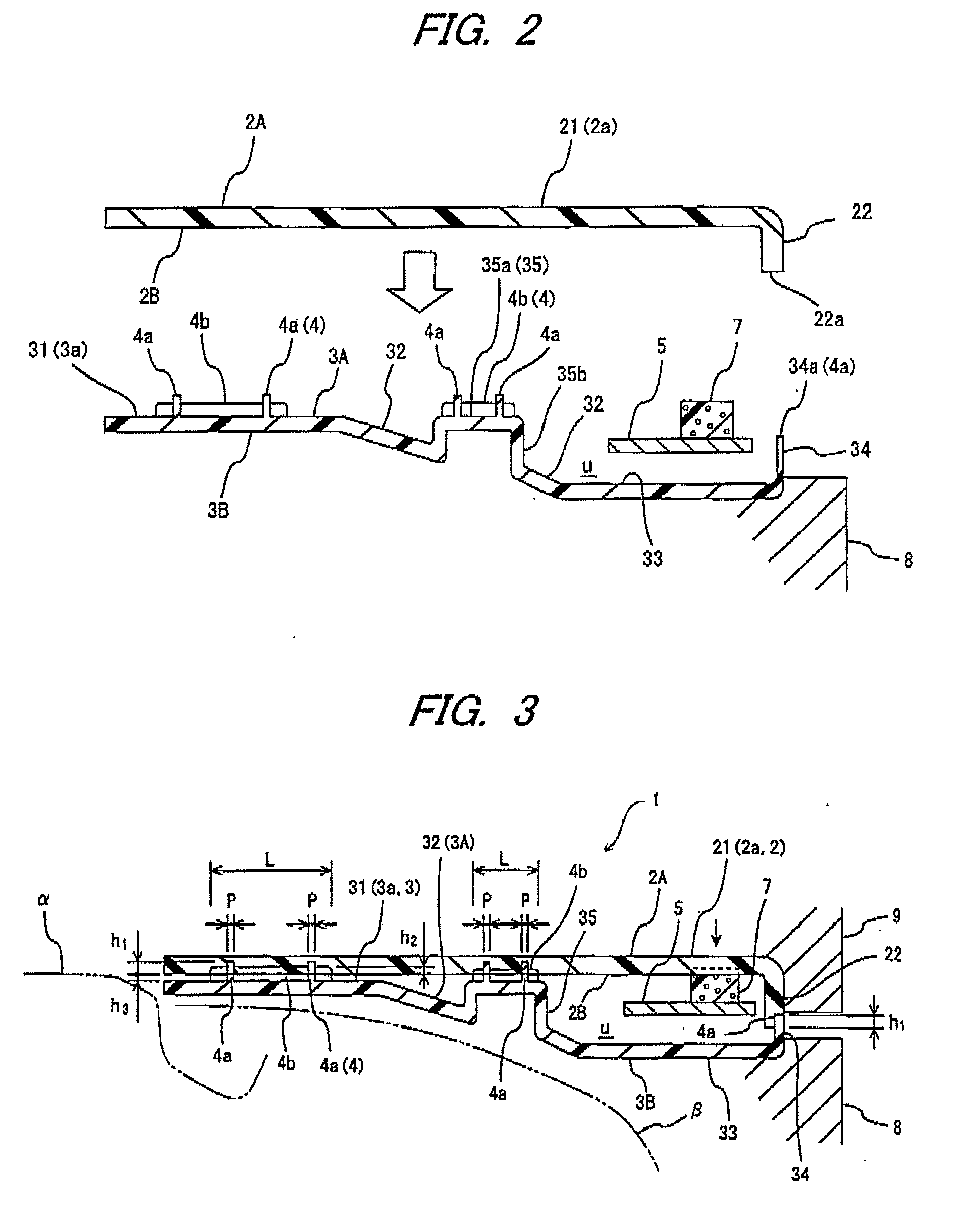
[0027]As illustrated in FIGS. 1 to 3, a spoiler 1 according to an exemplary embodiment includes a synthetic resin lower member 3 having welding ribs 4, and a synthetic resin upper member 2. The lower member 3 and the upper member 2 are joined together by welding to form the spoiler 1. The spoiler 1 has a wing-like configuration extending in a vehicle width direction, and is attached to a rear hatch β adjacent to a roof end a of an automobile, such as a minivan or a station wagon, as illustrated in FIG. 3. The spoiler 1 is two-toned. That is, the lower member 3 is black, and the upper member 2 is painted to have the same color as a vehicle body.

[0028]The upper member 2 is an injection-molded member forming an upper half of the spoiler 1. A main body 2a of the upper member 2 is elongated in the vehicle width direction, which is a direction perpendicular to the...


PUM


Abstract

A spoiler includes an upper member and a lower member. The upper and lower members are joined together by vibration welding. One of the upper and lower members includes a main welding rib and an auxiliary welding rib. Each of the main welding rib and the auxiliary welding rib is protruded toward the other of the upper and members so as to be vibration welded to the other of the upper and lower members. The main welding rib is arranged to extend along a vibration direction of the vibration welding, and the auxiliary welding rib is arranged to extend along a direction perpendicular to the vibration direction. A height of the auxiliary welding rib is less than a height of the main welding rib before the vibration welding. The auxiliary welding rib is spaced apart from the main welding rib.

Description

CROSS REFERENCE TO RELATED APPLICATION[0001]This application is a Divisional Application of application Ser. No. 12 / 838,702, filed Jul. 19, 2010, the disclosure of which is incorporated herein by reference.FIELD OF THE INVENTION[0002]The present invention relates to a spoiler of an automobile.DESCRIPTION OF RELATED ART[0003]A spoiler is attached, for example, to a roof end or a portion above a rear window of an automobile, such as a minivan or a station wagon, and extends in a vehicle width direction. Spoilers are formed to have a hollow configuration using a synthetic resin material. For example, spoilers may be formed by blow molding (see, e.g., JP 2007-62439 A and JP 2004-106765 A).[0004]Spoilers are often configured to accommodate, for example, an antenna, a wiper, etc. However, to arrange an antenna inside a blow-molded spoiler, a hole is bored in the spoiler, which increases the number of processes and raises a risk of damaging the antenna.[0005]With view to addressing such dr...

Claims


Application Information

Patent Timeline
Patent Type & Authority Applications(United States)
IPC IPC(8): B62D35/00
CPCB29C65/06B29C66/1122B29C66/1142B29C66/30223B29C66/727B29L2031/3456B62D35/007B29C66/545B29L2031/3058B29C66/8322Y02T10/82
Inventor EZAKA, HIDEKI
Owner INOAC CORP
Learn More