Magnetic resonance imaging apparatus

a magnetic resonance imaging and apparatus technology, applied in the field of magnetic resonance imaging apparatus, can solve the problems of reducing the maximum pulse width of conventional spsp pulses, increasing the minimum slice thickness, and reducing the spatial excitation profile. , to achieve the effect of achieving isotropic diffusion weighted images under typically used fov (24 cm)

Inactive Publication Date: 2012-11-01
GENERAL ELECTRIC CO
View PDF6 Cites 8 Cited by
  • Summary
  • Abstract
  • Description
  • Claims
  • Application Information

AI Technical Summary

Problems solved by technology

However, conventional SPSP pulses have their subpulses limited in maximum pulse width to a certain extent; therefore, they involve problems of degradation in a spatial excitation profile and increased minimum slice thickness.
This makes it difficult to acquire an isotropic diffusion-weighted image under typically used FOV (24 cm) and in-plane resolution (128×128) conditions.
In case of 3 T-MRI apparatus, the minimum slice thickness cannot be sufficiently reduced even with use of conventional SPSP pulses.
However, with the fat saturation method in Haase, sufficient fat suppression effect cannot be obtained as compared with methods using SPSP pulses.

Method used


Image

  • Magnetic resonance imaging apparatus
  • Magnetic resonance imaging apparatus
  • Magnetic resonance imaging apparatus

Examples


Embodiment Construction

[0023]Hereafter, description will be given to embodiments for carrying out the invention but the invention is not limited to the following embodiments.

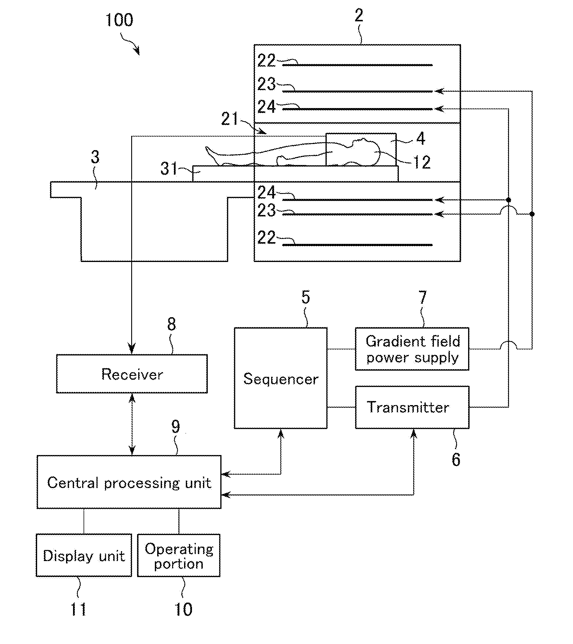
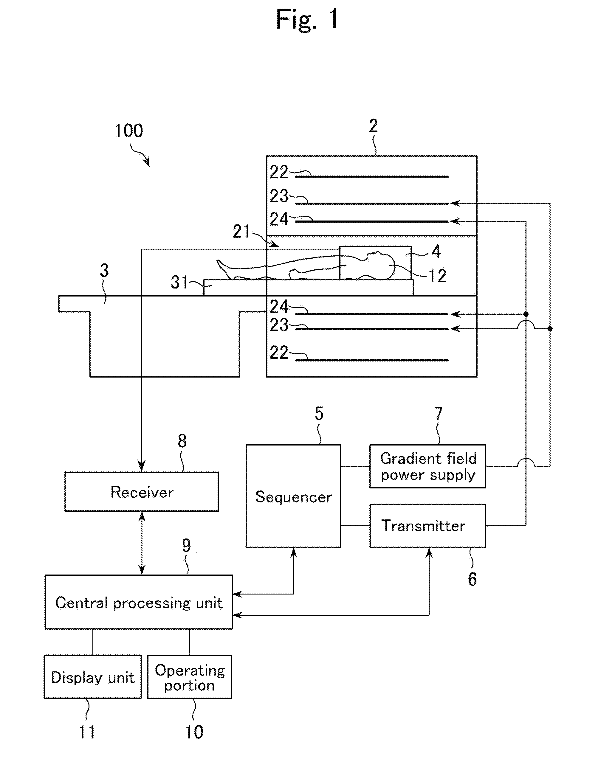
[0024]FIG. 1 is a schematic diagram of a magnetic resonance imaging apparatus 100.

[0025]The magnetic resonance imaging apparatus (hereafter, referred to as “MRI apparatus.” MRI: Magnetic Resonance Imaging) 100 includes a magnet 2, a table 3, a receiving coil 4, and the like.

[0026]The magnet 2 includes a bore 21 in which an object 12 is placed, a superconducting coil 22, a gradient coil 23, and a RF coil 24. The superconducting coil 22 applies a static magnetic field BO; the gradient coil 23 applies a gradient field; and the RF coil 24 transmits RF pulses. A permanent magnet may be used in place of the superconducting coil 22.

[0027]The table 3 has a cradle 31. The cradle 31 is so configured that it can be moved into the bore 21. The object 12 is carried into the bore 21 by the cradle 31.

[0028]The receiving coil 4 is attached to the hea...


PUM


Abstract

A magnetic resonance imaging apparatus that carries out a pulse sequence for making a signal of a first substance within an object smaller than a signal of a second substance within the object. The pulse sequence includes an α°-pulse for exciting the object, a refocus pulse for refocusing a phase of spin within a region excited by the α°-pulse, and a readout gradient field for acquiring a magnetic resonance signal from the region. The α°-pulse has a spectral selectivity such that a transverse magnetization of the first substance is made smaller than a transverse magnetization of the second substance. The refocus pulse has a spectral selectivity such that a phase of spin of the second substance is refocused and refocusing of a phase of spin of the first substance is suppressed.

Description

BACKGROUND OF THE INVENTION[0001]The present invention relates to a magnetic resonance imaging apparatus capable of carrying out a pulse sequence including α°-pulse and refocus pulse.[0002]There are known methods of using SPSP pulses (Spectral Spatial Pulses) as a fat suppression method. One such method is described in “Slice-Selective Fat Saturation in MR Angiography Using Spatial-Spectral Selective Prepulses,” by J. Forster, et al., Journal of Magnetic Resonance Imaging, Vol. 8, No. 3, pp. 583-589 (1998) (hereinafter referred to as “Forster”).[0003]SPSP pulses include multiple subpulses and are widely used in imaging using functional magnetic resonance imaging (fMRI), diffusion-weighted imaging, or the like. However, conventional SPSP pulses have their subpulses limited in maximum pulse width to a certain extent; therefore, they involve problems of degradation in a spatial excitation profile and increased minimum slice thickness. The maximum pulse width of a subpulse can be determ...

Claims


Application Information

Patent Timeline
Patent Type & Authority Applications(United States)
IPC IPC(8): G01R33/44
CPCG01R33/5607
Inventor LEE, SANGWOOWU, GAOHONG
Owner GENERAL ELECTRIC CO
Why Eureka
Try Eureka