Method and magnetic resonance device for imaging of particles

a magnetic resonance device and particle technology, applied in the field of particle imaging, can solve the problems of hypointense image regions, signal loss, susceptibility artifacts, etc., and achieve the effect of large contrast range and favorable detection of particl

Inactive Publication Date: 2011-08-04
SIEMENS HEALTHCARE GMBH
View PDF6 Cites 8 Cited by
  • Summary
  • Abstract
  • Description
  • Claims
  • Application Information

AI Technical Summary

Benefits of technology

[0021]The control unit controls at least one spectrally selective refocusing pulse that is generated after the excitation pulse at a generation of a spin echo in a non-resonant frequency range. An advantageous representation and / or an advantageous detection of the particle can be achieved since the magnetic resonance signal is composed only of signals from the refocused regions and thus covers a large contrast range in the acquired magnetic resonance images. Moreover, multiple spectrally selective refocusing pulses can be generated that are emitted after the excitation, and thus different ranges around the resonance frequency range can be selectively acquired and imaged.

Problems solved by technology

Particularly in T2*-weighted gradient echo sequences, the disruption of the homogeneous basic magnetic field leads to a signal loss.
In spin echo sequences, these interferences additionally lead to susceptibility artifacts.
A problem in this type of imaging of particles is that the hypointense image regions cannot be unambiguously associated with the particles since—as described above—there are multiple causes for a poor signal and the corresponding dark image regions.
However, these methods have the disadvantage that the inversion pulses in the spectral space have only an approximation of an ideal box shape and are fuzzy specifically at edges.
This leads to the situation that for the most part either a spectrally broadband saturation takes place, such that non-resonant signals are saturated as well, or a narrowband saturation takes place such that too much signal of the undisrupted water protons remains.
However, this excitation pulse is very fuzzy in the spectral space.

Method used


Image

  • Method and magnetic resonance device for imaging of particles
  • Method and magnetic resonance device for imaging of particles
  • Method and magnetic resonance device for imaging of particles

Examples


Embodiment Construction

[0026]A method and a magnetic resonance device 1 to image magnetically active particles that generate an interference field (for example a dipole field) in an applied basic magnetic field B0 are explained in more detail using the embodiments of the present invention that are explained in the following. The particles are formed by magnetically active particles that are or include iron oxide.

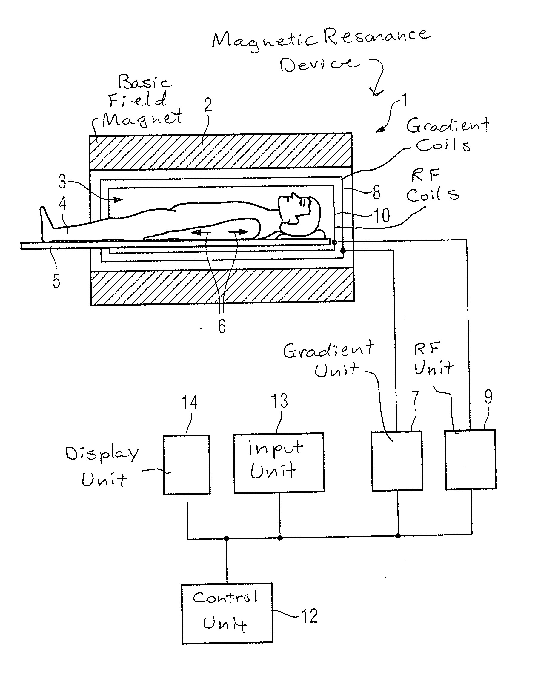
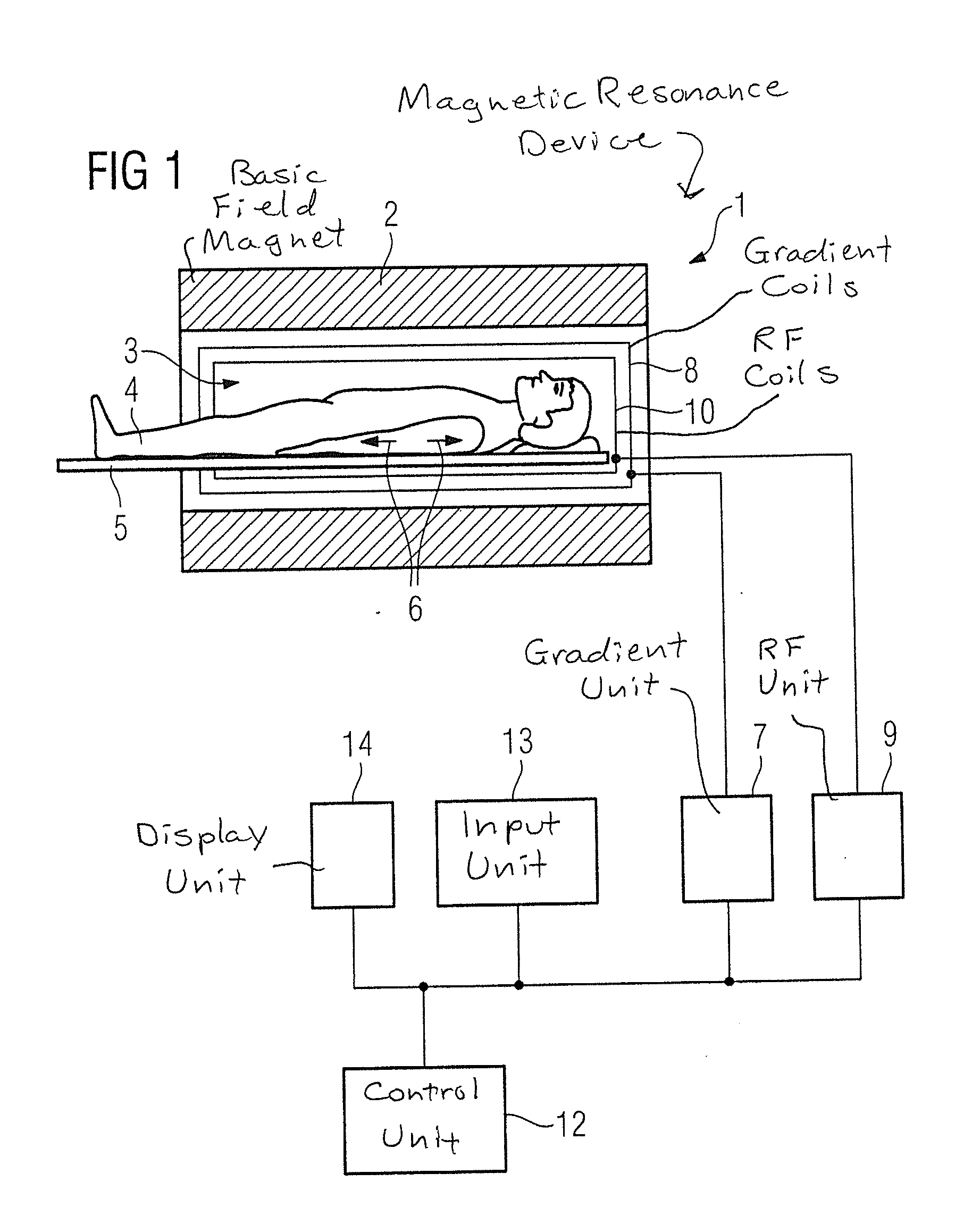
[0027]The magnetic resonance device 1 according to the invention is schematically depicted in FIG. 1. The magnetic resonance device 1 has a basic field magnet 2 that generates the basic magnetic field B0. The magnetic resonance device 1 additionally has a cylindrical acquisition region 3 to accommodate a patient 4, which acquisition region 3 is surrounded by a magnet 2 in a circumferential direction of the acquisition region 3. An examination subject (here a patient 4) can be shifted into the acquisition region 3 along a feed direction 6 (as this is indicated by arrows in FIG. 1) by means of a pat...


PUM


Abstract

In a magnetic resonance method and apparatus for imaging a particle that is located in an examination subject, a pulse sequence is emitted that includes an excitation pulse that generates a transverse magnetization of the examination subject from a magnetization appearing in a basic magnetic field, so the particle causes a magnetic interference field in the applied basic magnetic field in a magnetic resonance measurement. After the excitation pulse, at least one spectrally selective refocusing pulse is generated in a non-resonant frequency range at the generation of a spin echo.

Description

BACKGROUND OF THE INVENTION[0001]1. Field of the Invention[0002]The present invention concerns a method to image a particle that is located in an examination subject as well as a magnetic resonance device for this. In particular, the invention concerns the imaging of a particle that causes a magnetic interference field in an applied basic magnetic field during the acquisition of magnetic resonance data.[0003]2. Description of the Prior Art[0004]Magnetic resonance tomography is a wide-spread method for graphical representation of structures inside a body of a patient. To generate a magnetic resonance signal, in general protons of hydrogen molecules are excited that have been organized in a prepared magnetic state. Decay of this excitation induces a magnetic resonance signal in an acquisition coil. The magnetic resonance signal is thus dependent on (among other things) the density of the protons of the hydrogen molecules. A low magnetic resonance signal thus is obtained from regions t...

Claims


Application Information

Patent Timeline
Patent Type & Authority Applications(United States)
IPC IPC(8): G01R33/44
CPCG01R33/4828G01R33/5601G01R33/485
Inventor GRODZKI, DAVID
Owner SIEMENS HEALTHCARE GMBH
Why Eureka
Try Eureka