Method for obtaining amplitude and phase profiles of RF pulses for spatially selective excitation

a technology of applied in the field of obtaining amplitude and phase profiles of rf pulses for spatially selective excitation, to achieve the effects of improving excitation accuracy, reducing the length of excitation pulses, and widening the use rang

Active Publication Date: 2011-08-16
BRUKER BIOSPIN MRI +1
View PDF9 Cites 7 Cited by
  • Summary
  • Abstract
  • Description
  • Claims
  • Application Information

AI Technical Summary

Benefits of technology

[0008]Spatially selective excitation is a widely used technique in magnetic resonance imaging that is used to spatially restrict the transverse magnetization produced during excitation and / or to vary its amplitude and phase in the excitation volume. In slice selection, the most frequent case of selective excitation, the excitation volume is reduced to a defined slice. Multidimensional selective excitation, in which the excitation volume is restricted in more than one direction or the excitation is modulated in more than one direction, has also produced numerous applications. These include the excitation of a small three-dimensional volume inside a much larger object under examination for localized spectroscopy, the mapping of a selectively excited region of interest (ROI) with a reduced field of view (FOV) for the purpose of shortening the measurement time, the excitation of special volumes adapted to structures of the object under examination, or also the echo-planar imaging with reduced echo train lengths. Moreover, amplitude and phase modulation during excitation can also be used to compensate for disadvantageous effects of an inhomogeneous B1 field of the RF antennas used for transmission. This is an application that has recently become vastly more important due to the large increases in high-field MRI systems.
[0009]In the past, spatially selective excitation was usually performed by means of a single RF transmission antenna with an essentially homogeneous transmission field (B1 field) in conjunction with the gradient system. Inspired by the success of parallel imaging, in which signal acquisition is performed with a configuration of multiple RF reception antennas, termed an antenna array in the technical literature, it has since become common practice to also deploy such arrays for transmission in selective excitation. This permits partial replacement of the spatial encoding that is implemented in selected excitation, by analogy with acquisition by varying gradient fields, by so-called sensitivity coding, thus reducing the length of the excitation pulses. This uses the information contained in the different spatial variations of the transmission profiles of the individual array elements, hereafter also termed transmission profiles. Because the length of such selective excitation pulses has usually been one of the limiting criteria for the applicability of this technique, parallel excitation (PEX) is a promising method to enable wider use of spatially selective excitation than has so far been possible.
[0010]One of the basic questions in the deployment of spatially selective excitation is the determination of the RF pulses that have to be emitted by the RF transmission system to generate the desired excitation pattern in conjunction with the k-space trajectory produced by the gradients. In the article “A k-space analysis of small tip-angle excitation” [1], Pauly et al. describe a method for one-channel spatially selective excitation with which the sought pulse shape B1 (t) can be calculated based on a mathematical analogy of the selective excitation with Fourier imaging essentially by means of a Fourier transform of the desired excitation pattern and sampling of the Fourier-transform along the defined k-space trajectory. Katscher et al. extended this calculation method to the case of an antenna array with multiple independent transmission channels [2].
[0011]However, the decisive disadvantage of the calculation methods described in these articles is that diverse experimental factors that can negatively influence accurate implementation of the excitation and manifest themselves in artifacts, depending on the specific k-space trajectory, are not or cannot be taken into account in the calculation. One example of such influencing factors are inhomogeneities of the basic magnetic field that cause the resonance frequency of the nuclear spins to no longer match the irradiated RF frequency at certain locations of the object under examination (causing off-resonances). Further factors include the relaxation of the spin system during the pulses and the deviation of the real k-space trajectory from its theoretical form defined in the calculation because of technical imperfections of the gradient system and physical interference factors such as induced eddy currents.
[0012]As a result of these disadvantages, further methods for pulse calculation for spatially selective excitation have gradually come about. In some works [3, 4], the conjugate-phase (CP) method from image reconstruction was used, which can take off-resonance effects into account and correct them to some degree. Despite the CP method's ability to correct off-resonance effects, these conventional methods for pulse calculation are less than optimal in a number of respects. The algorithms generally result in pulses that do not optimally achieve accurate implementation of the desired excitation pattern, in particular, if the k-space trajectory exhibits a degree of under-sampling or if the off-resonance influences exhibit pronounced spatial variation. A more recent method for pulse calculation introduced by Yip et al. [5] and generalized for multi-channel transmission by Grissom et al. [6], is based on an optimization method and achieves improvements in excitation accuracy in two respects. On the one hand, it is more robust than under-sampling the k-space, on the other hand, it is a simple way of taking off-resonance influences into account in pulse calculation. Moreover, it provides the possibility of including further constraints in the calculation, such as control of the integrated or also the maximum RF transmission power, which is important for SAR (specific absorption rate) control or technical restrictions on the RF power transmitters.
[0013]A general additional problem with these new methods is that relatively precise maps of the basic magnetic field variations have to be initially acquired in the region of the object under examination in order to correct for off-resonance effects. This is often difficult, especially in in-vivo conditions. To also compensate for effects of transverse relaxation in pre-calculation with these methods, which is possible in theory although not explicitly mentioned in the relevant publications, detailed determination of the spatial dependence of the T2* relaxation times within the object under examination is also required in this case.

Problems solved by technology

However, this is only appropriate if it can be ensured that the progression of the k-space trajectory before this instant does not have any substantial effect on the trajectory after this instant.

Method used


Image

  • Method for obtaining amplitude and phase profiles of RF pulses for spatially selective excitation
  • Method for obtaining amplitude and phase profiles of RF pulses for spatially selective excitation
  • Method for obtaining amplitude and phase profiles of RF pulses for spatially selective excitation

Examples


Embodiment Construction

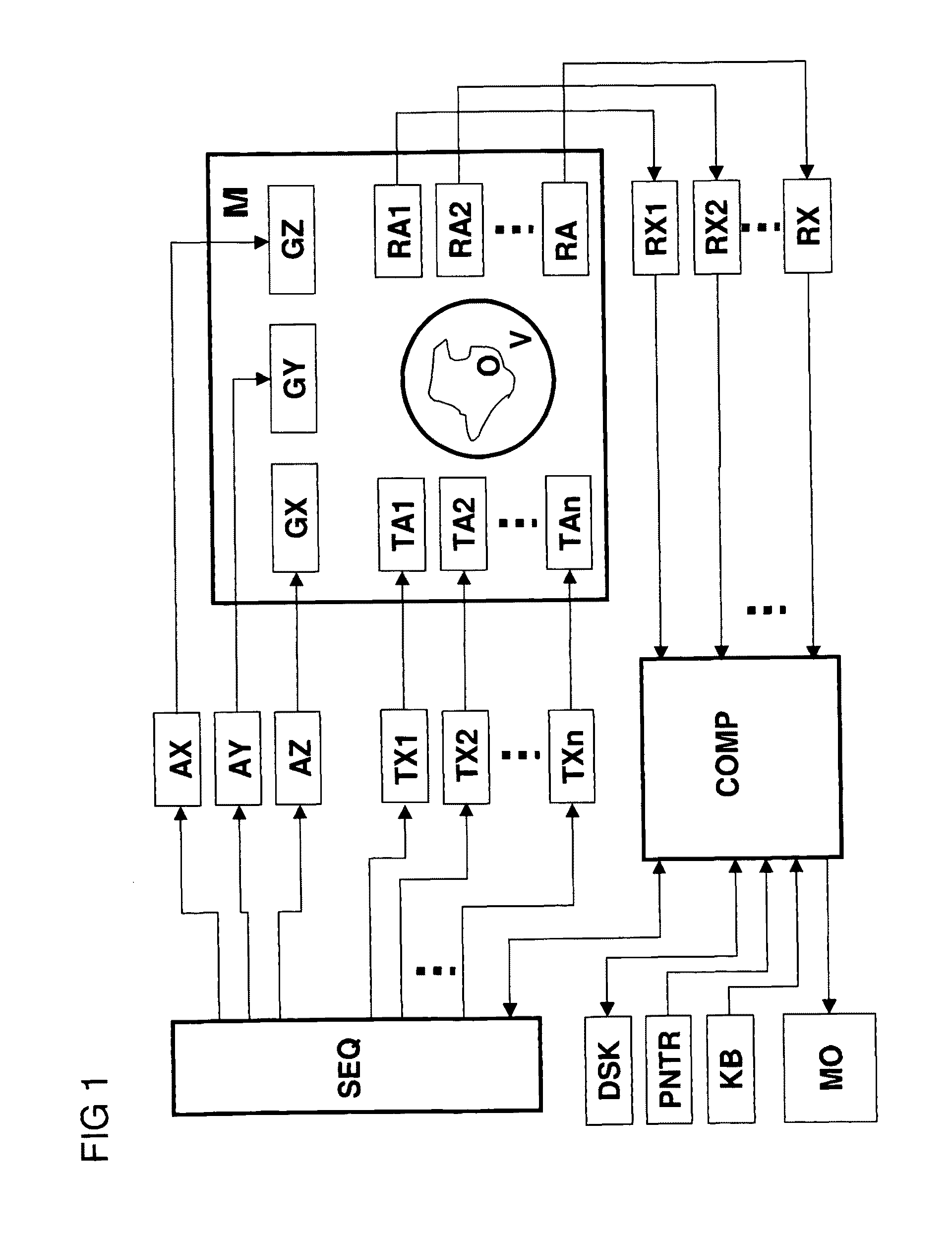
[0041]FIG. 1 shows a schematic view of an MR measurement system that is suitable for performing the inventive method. The system contains a main magnet M, with which the essentially homogeneous and static basic magnetic field is produced in an examination volume V. Three sets of gradient coils GX, GY, and GZ surround this examination volume V and are put into the bore of the main magnet M to superpose additional magnetic fields with constant gradients of controllable duration and strength on the basic field. Gradient amplifiers AX, AY, and AZ are switched by the sequence control unit SEQ to produce gradient pulses at the right instant. The gradient coils GX, GY, GZ are supplied with electrical power to produce the essentially linear gradient fields.

[0042]Within the gradient field system, there are multiple RF transmission antennas TA1 to TAn that are collectively termed a transmission array comprising n elements. They surround an object under examination O and are powered from multi...


PUM


Abstract

A method for determining amplitude and phase dependencies of radio frequency pulses that are irradiated during traversal of a defined k-space trajectory to produce a spatial pattern of the transverse magnetization in an MR experiment using at least one RF transmission antenna, is characterized in that, in a calibration step, a set of basic pulses is defined, each basic pulse is irradiated individually, the specified k-space trajectory is traversed and at least one set of basic patterns is produced by detection of the MR signals thus excited, which in a range to be examined of the object, are proportional to the complex transverse magnetization produced, wherein the k-space trajectory is traversed fully identically every time at least from the beginning of the irradiation of each basic pulse, and, in a calculation step, a defined target pattern is approximated with a linear combination of the basic patterns of a set or with a mathematical association of linear combinations, with which, within each set, the basic patterns are identically combined, and the amplitude and phase dependencies to be determined are obtained as the corresponding linear combination of the basic pulses. Experimental imperfections can be intrinsically compensated for in this way.

Description

[0001]This application is the national stage of PCT / DE2007 / 002183 filed on Dec. 5, 2007 and also claims Paris Convention priority to DE 10 2006 012 058 162.8 filed Dec. 9, 2006.BACKGROUND OF THE INVENTION[0002]The invention relates to a method for determining amplitude and phase dependencies of RF pulses that, while passing through a defined k-space trajectory to produce an n-dimensional spatial pattern (n>=1) of the transverse magnetization, are irradiated into an object by means of at least one RF transmission antenna of a magnetic resonance measurement system (MR measurement system) as part of a spatially resolved magnetic resonance experiment.[0003]Such a method is known, for example, from [6].[0004]Magnetic resonance imaging (MRI), also known as magnetic resonance tomography (MRT), is a widely used technique for non-destructive acquisition of images of the interior of an object under examination and is based on the spatially resolved measurement of magnetic resonance signals...

Claims


Application Information

Patent Timeline
Patent Type & Authority Patents(United States)
IPC IPC(8): G01V3/00
CPCG01R33/4836G01R33/5612G01R33/583G01R33/5611G01R33/586
Inventor ULLMANN, PETER
Owner BRUKER BIOSPIN MRI
Why Eureka
Try Eureka