Magnetic resonance imaging apparatus and magnetic resonance imaging method

a magnetic resonance imaging and apparatus technology, applied in the field of magnetic resonance imaging, can solve the problems of distorted magnetic field of gantry end units and interference in diagnosis, and achieve the effect of suppressing cusp artifacts

Inactive Publication Date: 2017-08-10
HITACHI LTD
View PDF0 Cites 6 Cited by
  • Summary
  • Abstract
  • Description
  • Claims
  • Application Information

AI Technical Summary

Benefits of technology

[0025]According to the present invention, it is possible to suppress a cusp artifact without depending on a imaging condition, such as a slice thickness or an FOV.

Problems solved by technology

However, in the short gantry type MRI apparatus, as a space having a uniform static magnetic field, and a gradient magnetic field linear region are narrow, a magnetic field of a gantry end unit is distorted.
There are many cases where the cusp artifact is generated in spin echo imaging of a sagittal (SAG) and coronal (COR) section in which the Z-axis is set in the phase encoding direction, and there is a case where diagnosis is interfered.

Method used


Image

  • Magnetic resonance imaging apparatus and magnetic resonance imaging method
  • Magnetic resonance imaging apparatus and magnetic resonance imaging method
  • Magnetic resonance imaging apparatus and magnetic resonance imaging method

Examples


first embodiment

[0043]Hereinafter, an example of embodiments of the present invention will be described with reference to the attached drawings. In addition, in all of the drawings for describing the embodiments of the invention, basically, those having the same functions are given the same reference numerals, and the repeating description will be omitted.

[0044][Block Diagram of MRI Apparatus]

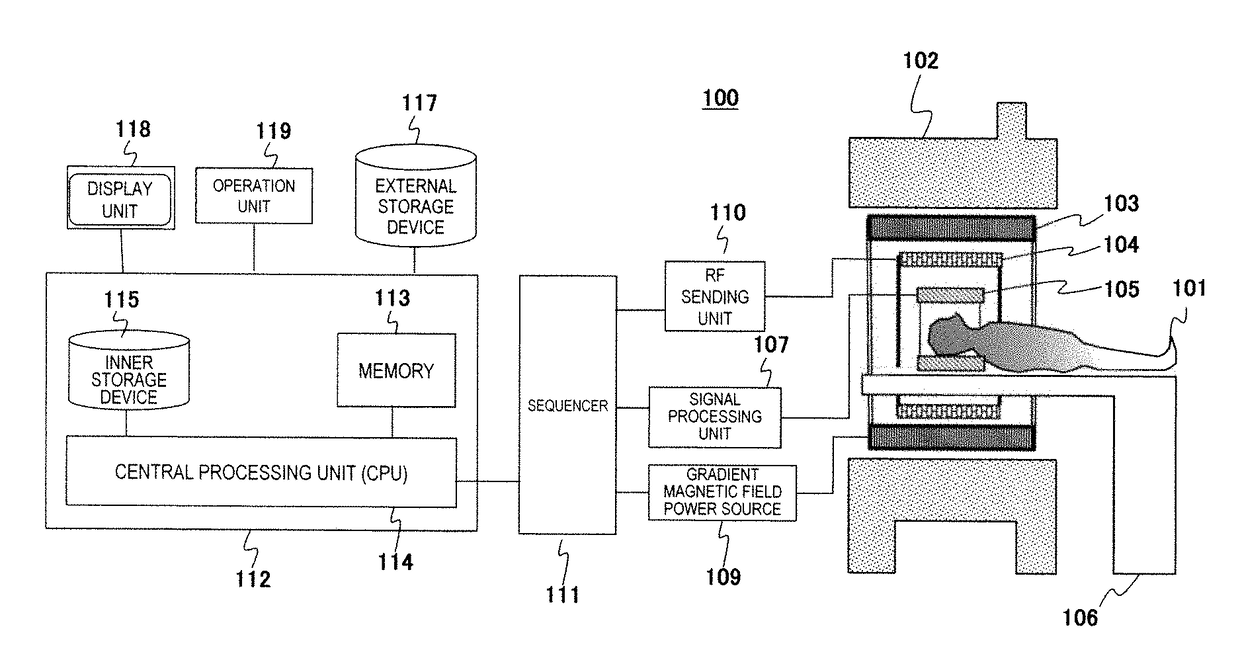
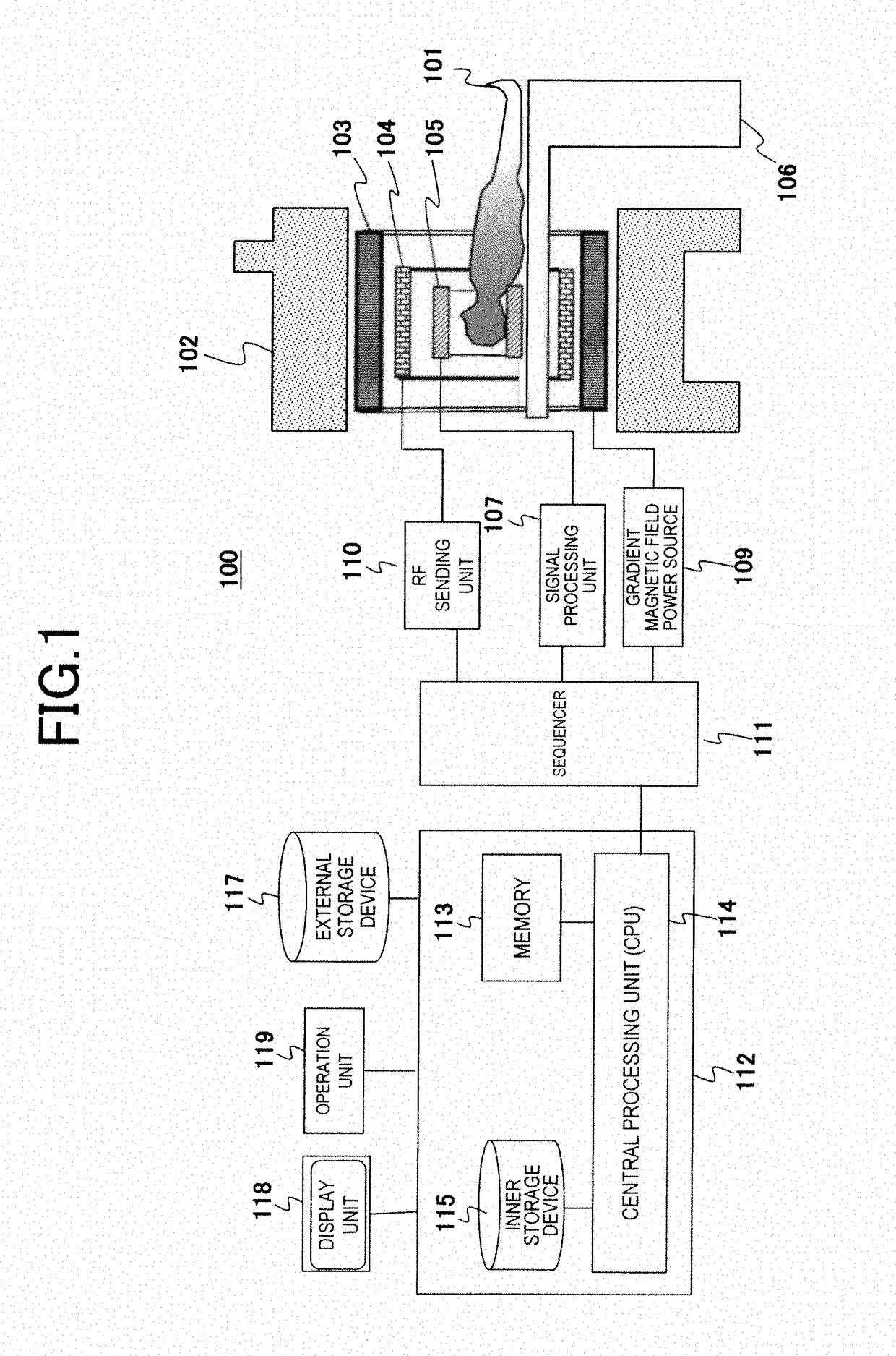
[0045]First, an MRI apparatus of the embodiment will be described. FIG. 1 is a block diagram illustrating the entire configuration of an example of an MRI apparatus 100 of the embodiment. The MRI apparatus 100 of the embodiment obtains a tomographic image of an object 101 by using an NMR phenomenon, and as illustrated in FIG. 1, the MRI apparatus 100 includes a static magnetic field generation source 102, a gradient magnetic field coil 103 and a gradient magnetic field power source 109, a high frequency magnetic field (RF) sending coil 104 and an RF sending unit 110, an RF receiving coil 105 and a signal proce...

example

[0136]As illustrated in FIGS. 3(a) and 3(b), the magnetic field distortion position 210 is at a position of ±250 mm in the Z-axis direction. The CASD gradient magnetic field (323odd, 323evn) is applied so that the phase shift becomes 1 / 4·π [rad] at the magnetic field distortion position 210 (±250 mm), the instrumentation is performed two times, and the spatial signal dispersion in a case of the echo signal to which the echo signal to which the obtained data is added is added, is illustrated in FIGS. 14(a) to 14(f). FIGS. 14(a) to 14(f) respectively illustrate the signal intensity and the phase which are similar to those of FIGS. 8(a) to 8(f). In addition, in FIGS. 14(a) to 14(c), a vertical axis is a signal intensity and a horizontal axis is a position in the Z-axis direction (distance from the original point: Distance [mm]). In addition, in FIG. 14(d) to 14(f), a vertical axis is a phase, and a horizontal axis is a position in the z-axis direction (Distance [mm]).

[0137]As illustrat...

second embodiment

[0178]Next, a second embodiment of the present invention will be described. In the first embodiment, the NSA which is the number of times of repetition is an even number, the instrumentation of which the polarity of the CASD gradient magnetic field (323odd, 323evn) is reversed is alternately executed, and by the addition, an image in which the echo signal from the magnetic field distortion position is suppressed is obtained. Meanwhile, in the embodiment, from the result of the instrumentation executed one time, an image in which the echo signal from the magnetic field distortion position is suppressed is obtained. Therefore, even when the NSA which is the number of times of repetition is an odd number, this case can be employed.

[0179]An MRI apparatus of the embodiment is basically the same as the MRI apparatus 100 of the first embodiment. However, a configuration of the CAS sequence which the instrumentation unit 130 follows is different. Hereinafter, the embodiment will be describe...


PUM


Abstract

In a sequence of emitting a plurality of refocus RF pulses after one excitation RF pulse, in order to suppress a cusp artifact at a known magnetic field distortion generation position regardless of an imaging condition, such as a slice thickness or an FOV, between an excitation RF pulse and an initial refocus RF pulse, by generating a phase shift to transverse magnetization at the position, and by applying an extremely small dephase gradient magnetic field in the phase encoding direction and / or in the slice encoding direction, a signal value of an NMR signal (echo signal) is suppressed at the position, and the cusp artifact is deteriorated.

Description

TECHNICAL FIELD[0001]The present invention relates to a magnetic resonance imaging (hereinafter, referred to as MRI) technology, particularly to a technology of suppressing an artifact generated by ununiformity of a static magnetic field and non-linearity of a gradient magnetic field.BACKGROUND ART[0002]In a horizontal magnetic field MRI apparatus, a short gantry type MRI apparatus of which a Z-axis length (magnetic field direction) of a gantry is shortened for considering opening feeling of an object important, is mainly used. However, in the short gantry type MRI apparatus, as a space having a uniform static magnetic field, and a gradient magnetic field linear region are narrow, a magnetic field of a gantry end unit is distorted. Under the influence of distortion of the magnetic field outside an imaging FOV, in the imaging FOV, a bright spot having high brightness or an artifact having a shape of a crescent moon, is generated. These are called a cusp artifact.[0003]There are many ...

Claims


Application Information

Patent Timeline
Patent Type & Authority Applications(United States)
IPC IPC(8): G01R33/565G01R33/387A61B5/055
CPCG01R33/5659G01R33/387A61B5/055G01R33/5617G01R33/56563G01R33/56572
Inventor HIRAI, KOSUKE
Owner HITACHI LTD
Why Eureka
Try Eureka