Anaesthesia and consciousness depth monitoring system

a depth monitoring and anaesthesia technology, applied in the field of evoked electrophysiological potential signal monitoring, can solve the problems of severe signal disturbances during critical, inability to discriminate between crucial short-term versus long-term memory functions implicated in intraoperative recall, and inadvertent combining of distinctively different signal groups, so as to minimize unwanted external signal interference

Active Publication Date: 2012-11-01
BURTON DAVID
View PDF7 Cites 118 Cited by
  • Summary
  • Abstract
  • Description
  • Claims
  • Application Information

AI Technical Summary

Benefits of technology

[0091]a sample and window timing device enabling the aperture window to be delayed so as to minimize unwanted external signal interference;
[0092]a sample and window timing device enabling the aperture window delay and width to be controlled so as to minimize unwanted external signal interference.

Problems solved by technology

While conventional anaesthesia monitoring mainly relies on the forehead monitoring of electromyography (EMG) originating from facial muscles, the close proximity of these signals to EEG signals can lead to the inadvertent combining of these distinctively different signal groups.
In particular, severe signal disturbances were found to occur during critical phases of anaesthesia, including fast consciousness transitions and deep anaesthesia electrosurgical periods.
Failure to effectively distinguish between these 2 states can result in awareness during anaesthesia-induced muscle suppression.
Despite the widespread deployment of Ramsay, OAA / S and other popular clinical scales, these tools cannot discriminate between crucial short-term versus long-terms memory functions implicated during intraoperative recall.
Patients are susceptible to a range of adverse incidents during anaesthesia which can temporarily or permanently affect cognition, including oxygen deprivation, excessive anaesthesia (linked to mortality rates), insufficient anaesthesia (can result in intraoperative awareness and PTSD), or restricted circulation of respiratory function (can lead to cognitive impairment).

Method used


Image

  • Anaesthesia and consciousness depth monitoring system
  • Anaesthesia and consciousness depth monitoring system
  • Anaesthesia and consciousness depth monitoring system

Examples


Embodiment Construction
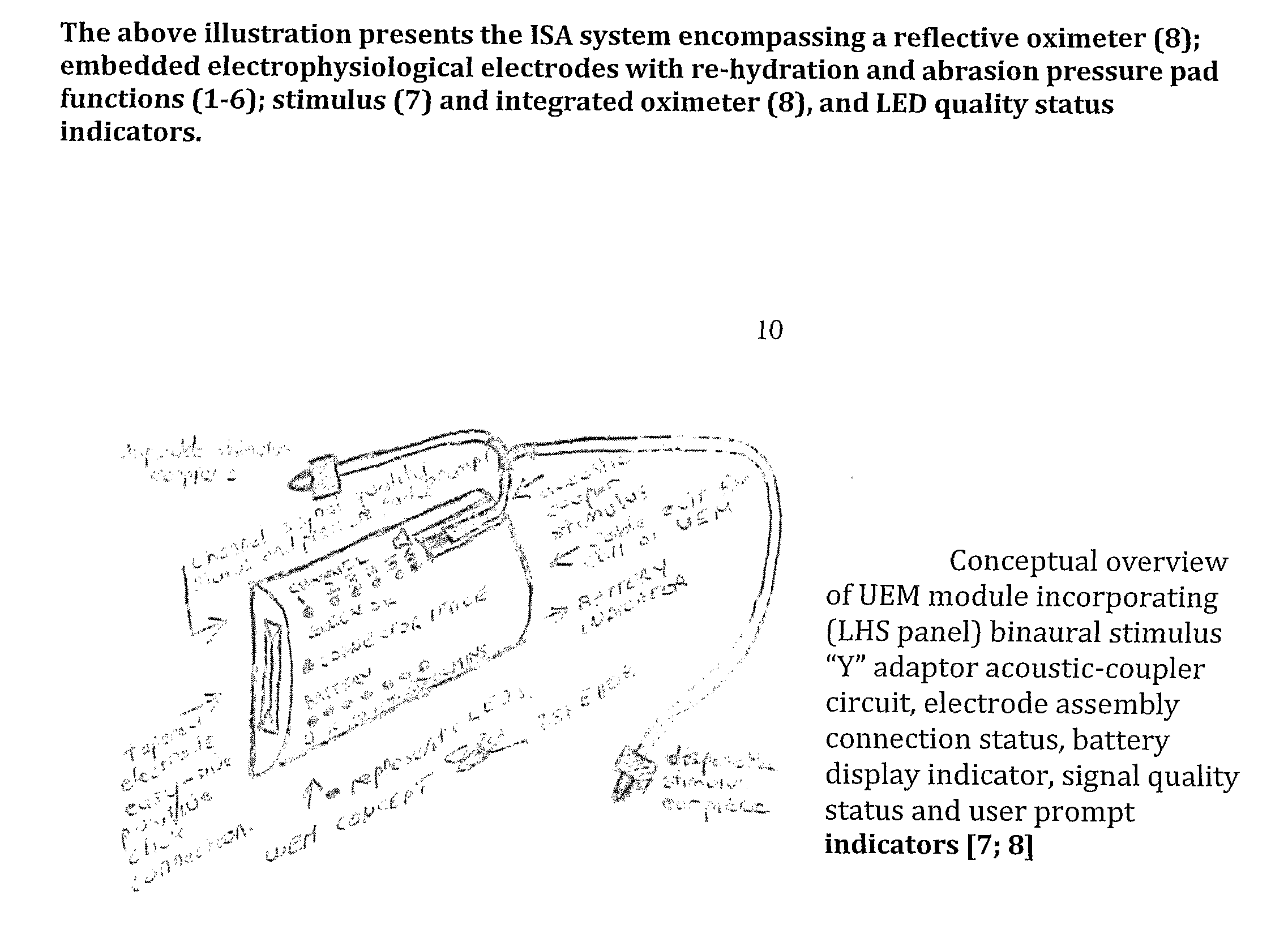
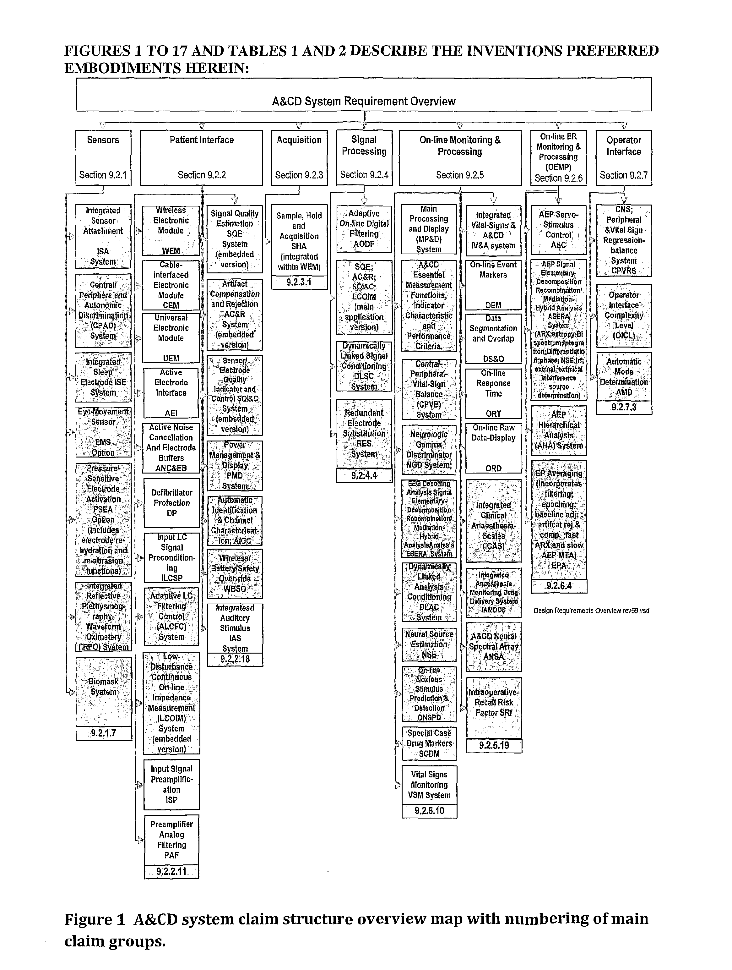
[0113]FIG. 1:

[0114]FIG. 1 decomposes the system into seven subsystems, each subsystem further decomposed into a number of components. Each of these subsystems and the affiliated components will be described in the form of systems requirements. Green blocks represent systems inventions.
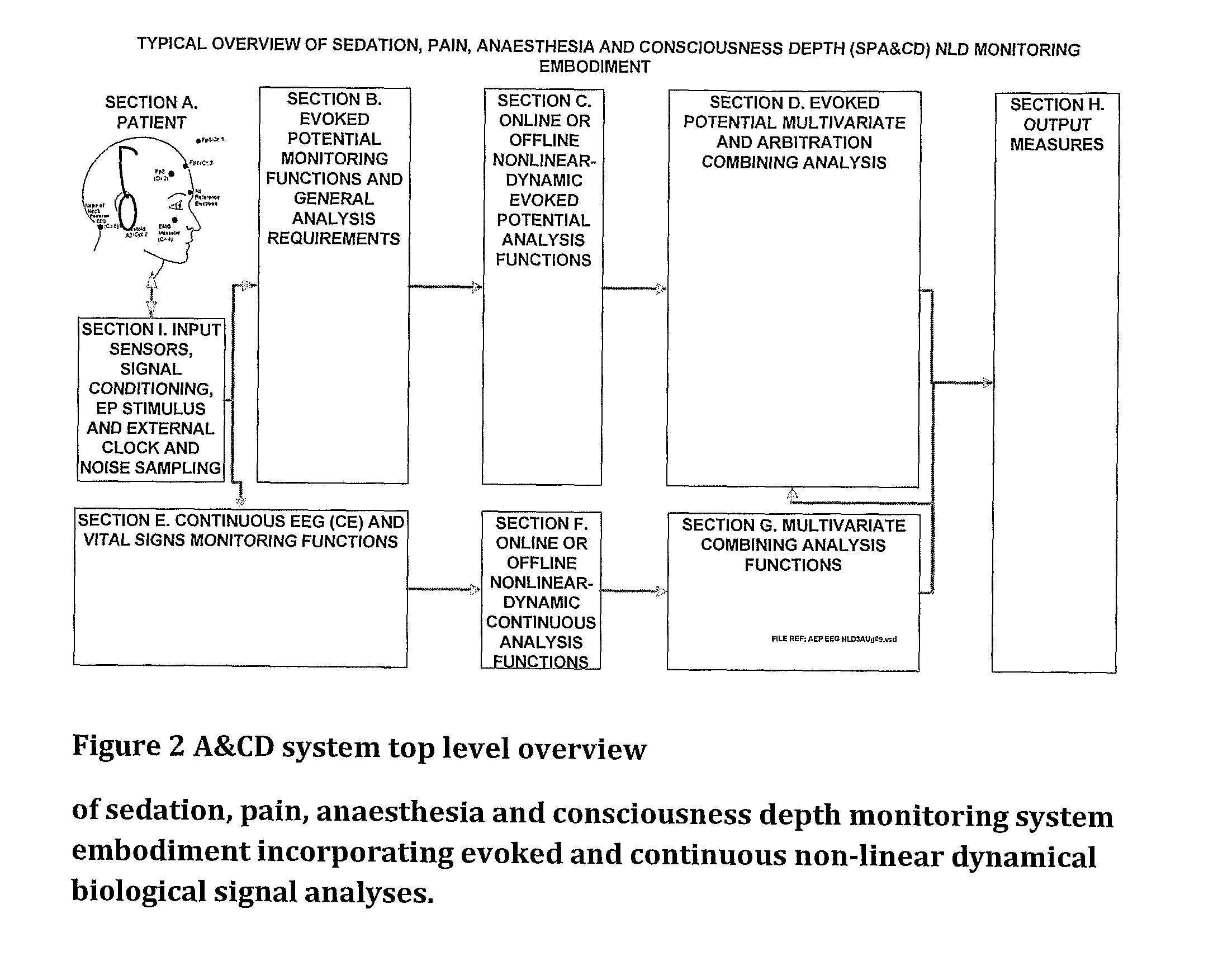
[0115]FIG. 2:

[0116]FIG. 2 presents a high level overview of a typical A&CD system embodiment. Section A shows the patient monitored signals via the patient-applied sensor or the so called integrated sensor attachment device, which is typically applied to the patients forehead and facial regions. A stimulus signal is generated and applied to the patient in order to evoked the desired patient-responses fro further processing. The patient sensor-monitored signals are signal conditioned then input to section E where the evoked potential monitoring functions are applied to the evoked signals, and to section E where the continuously monitored signals are further processed. Section C applies special non-linea...


PUM


Abstract

Methods and systems incorporating non-linear dynamic (NLD) analysis such as entropy or other complexity analysis monitoring continuous or evoked signals from a biological subject are presented, where such a system comprises of processing steps including: a) the combination of a biological signal evoked as a result of patient stimulation presented to a biological subject and a non-linear analysis method capable of capturing temporal changes in signal order or regularity; b) any combination of processed evoked or continuous central nervous or peripheral physiological mechanisms b) a means to generate a measure indicative of a patient's level of anaesthesia and consciousness depth (A&CD), sedation or sleep/wake state. Methods and systems incorporating a NLD analysis means to improve the discrimination between different signals origins including any combination of: a) central nervous system (CNS), b) peripheral control or nervous system (PNS), c) autonomic control or nervous system (ANS), d) arousals, and e) artifacts.

Description

FIELD OF INVENTION[0001]The present invention relates to the field of evoked electrophysiological potential signal monitoring and in particular can be applied as a means to determine the sentient state of an individual, and as a means to authenticate the physiological, electrical or electromagnetic source of a signal.BACKGROUND OF INVENTION[0002]The process of monitoring the sentient state of a subject is an essential pre-requisite to reliable tracking of many physiological parameters or the effective clinical deployment of many monitoring systems.[0003]Additionally, and in the context of general monitoring of physiological signals, the requirements to distinguish the source of a signal can be a critical step. In particular, a physiological monitoring system output measure typically relies upon the assumption that the output measure is predominantly based on a known source of interest. In the case of cerebral monitoring during anaesthesia, for example, output measurement indices rel...

Claims


Application Information

Patent Timeline
Patent Type & Authority Applications(United States)
IPC IPC(8): A61B5/0484A61B5/0488A61B5/00A61B5/04A61B5/375
CPCA61B5/0205A61B5/7275A61B5/02125A61B5/02405A61B5/0402A61B5/0476A61B5/0484A61B5/0488A61B5/0496A61B5/08A61B5/14542A61B5/415A61B5/4821A61B5/4839A61B5/7203A61B5/7207A61B5/7257G06F19/3431A61B5/02116A61B5/4029A61B5/4064A61B5/4088A61B5/4047G16H50/30A61B5/325A61B5/318A61B5/377A61B5/369A61B5/389A61B5/398A61B5/372A61B5/38A61B5/397A61B5/346A61B5/721A61B5/7285G01R29/26
Inventor BURTON, DAVID
Owner BURTON DAVID
Why Eureka
Try Eureka