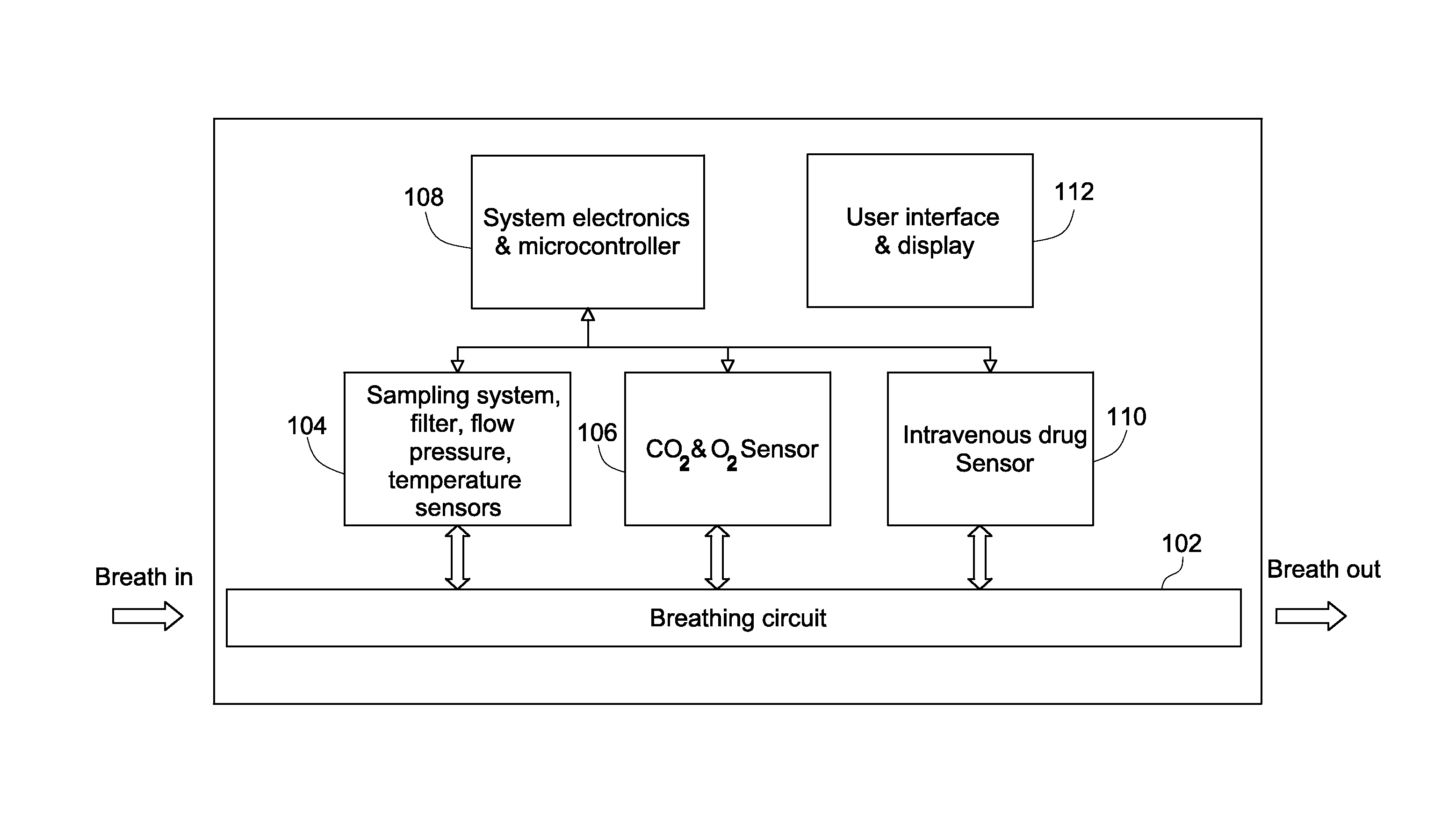
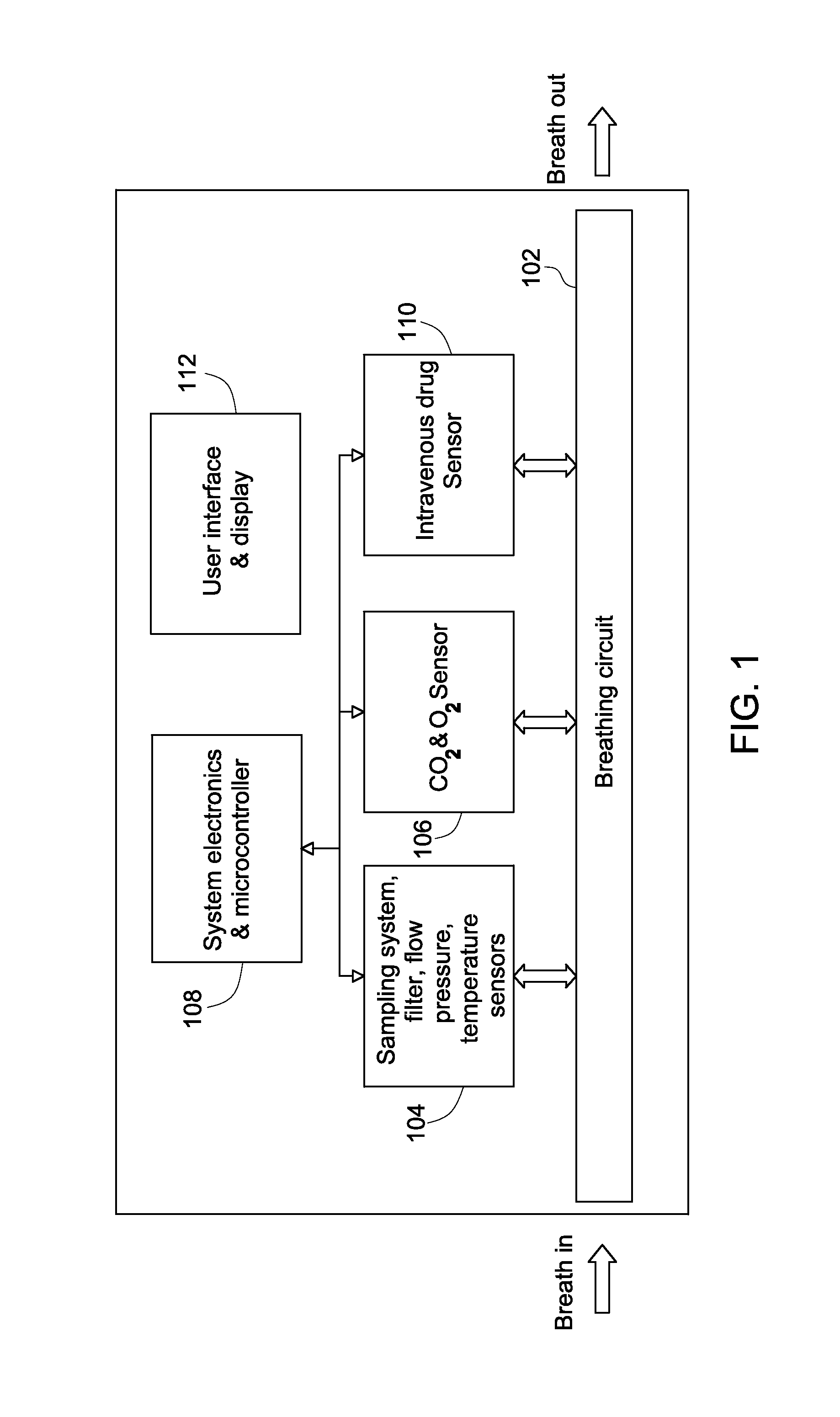
Systems for intravenous drug monitoring
a drug monitoring and system technology, applied in the field of intravenous anesthesia drug monitoring, can solve the problems of inability to achieve pharmacokinetic models, time-consuming and expensive, and inability to direct measure drugs in plasma
- Summary
- Abstract
- Description
- Claims
- Application Information
AI Technical Summary
Benefits of technology
Problems solved by technology
Method used
Image
Examples
example 1
[0044]
Cp=a·Cb+b eq (1)
[0045]In this example, the only input of the transfer function is Cb on the right side of the equation. The output of the transfer function is the plasma concentration of the drug Cp on the left side of the equation. “a” is a fitting parameter multiplied to Cb, and “b” is a fitting parameter to compensate for any offset between drug concentration in breath sample and drug concentration in plasma. The a and b are empirical numbers established from experiments, where the drug concentrations in breath sample are measured from patients. Linear regression fitting is used to extract the numerical value of fitting parameters a and b. Once a and b are established with enough statistical confidence, eq (1) may be used to predict plasma concentration of the target drug if the breath concentration of the drug is measured. Eq (1) is the simple transfer function with only first order terms. In real application, it provides the benefit of a simple numerical calculation, re...
example 2
[0046]
Cp=a·Cb+b·Cb2+c eq (2)
[0047]In this example, the input of the transfer is just the breath drug concentration Cb on the right side of the equation. The output of the transfer function is the plasma concentration of the drug Cp on the left side of the equation. a is a fitting parameter multiplied to Cb, b is the second order fitting parameter multiplied to the square of the breath drug concentration, and c is a fitting parameter to compensate for offset. The fitting parameters are established empirically. One difference between eq (2) and eq (1) is the addition of a second order term, which provides better prediction accuracy but typically requires more computing power and data storage space.
example 3
[0048]
Cp=[(a·Cb) / Cco2]+b. eq (3)
[0049]In this example, the inputs of the transfer function are the breath drug concentration Cb and the exhaled end tidal carbon dioxide concentration CCO2 on the right side of the equation. The output of the transfer function is the plasma concentration of the drug Cp on the left side of the equation. a is a fitting parameter multiplied to the division product of the breath drug concentration to the end tidal carbon dioxide concentration. b is a fitting parameter to compensate for offset. Both a and b are empirical fitting parameters extracted from measured plasma drug concentration, breath drug concentration and end tidal carbon dioxide concentration. Once fitting parameters a and b are established with enough statistical confidence, eq (3) may be used to predict plasma drug concentration with the input of measured breath drug concentration and end tidal carbon dioxide concentration. In this transfer function, end tidal carbon dioxide concentratio...
PUM
 Abstract
Description
Claims
Application Information
 - R&D
- Intellectual Property
- Life Sciences
- Materials
- Tech Scout
- Unparalleled Data Quality
- Higher Quality Content
- 60% Fewer Hallucinations
Browse by: Latest US Patents, China's latest patents, Technical Efficacy Thesaurus, Application Domain, Technology Topic, Popular Technical Reports.
© 2025 PatSnap. All rights reserved.Legal|Privacy policy|Modern Slavery Act Transparency Statement|Sitemap|About US| Contact US: help@patsnap.com


