Method and apparatus for visual stimulation and recording of the pattern electroretinogram of the visual evoked potentials

a technology of visual evoked potentials and electroretinograms, which is applied in the field of visual stimulation and recording of pattern electroretinograms (perg) and visual evoked potentials (vep), can solve the problems of not optimizing the duration of examination, affecting the signal-to-noise ratio, and using more complex visual stimulation techniques, so as to reduce the recording time and reduce the time

Inactive Publication Date: 2012-11-01
INGENESI DI GUALTIERO REGINI
View PDF1 Cites 2 Cited by
  • Summary
  • Abstract
  • Description
  • Claims
  • Application Information

AI Technical Summary

Benefits of technology

[0012]A main advantage of the present invention with respect to conventional testing methods is to minimise the recording times of transient and steady-state PERG on two hemifields, since the stimuli are administered simultaneously, rather than in subsequent times.
[0013]The examination of the electrophysiological response of the visual field is thus reduced to only two sessions of stimulation, at the end of which there are four responses, two of transient type and two of steady-state type for two visual hemifields.
[0014]A further advantage of the present invention is to allow to examine a greater number of areas of the visual field, and then to have a more detailed mapping of functional vision, with an advantage consisting, also in this case, in a reduction of time with respect to traditional methods.
[0015]Furthermore, an advantage of the present invention is to

Problems solved by technology

However there is a drawback in recording electrofunctional responses from two or more areas of the visual field that consists of recording said responses in subsequent times. If e.g. the central viewing area called EE is divided in two hemifields, a lower one called Ei and an upper called Es, just one hemifield at a time is stimulated, equal to 50% of the entire area, while the other hemifield is maintained at a constant illumination; it follows that the duration of the examination of two hemifields Ei and Es is double, with respect to the recording of the whole central visual area EE.
Furthermore, as known, the halving of the stimulated surface worsens the signal-to-noise ratio.
Further, the use of more comple

Method used


Image

  • Method and apparatus for visual stimulation and recording of the pattern electroretinogram of the visual evoked potentials
  • Method and apparatus for visual stimulation and recording of the pattern electroretinogram of the visual evoked potentials
  • Method and apparatus for visual stimulation and recording of the pattern electroretinogram of the visual evoked potentials

Examples


Embodiment Construction

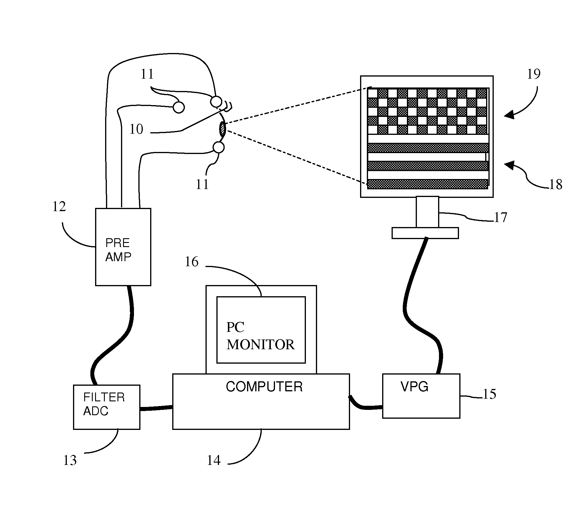
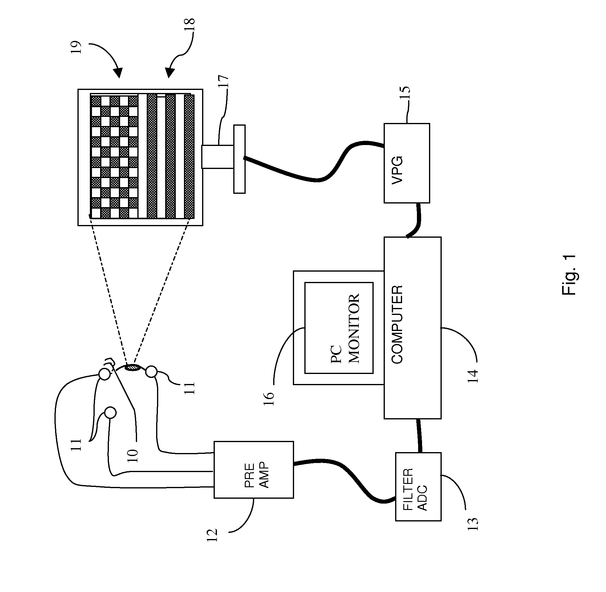
[0021]For embodying the invention, it is necessary to use a means of visual stimulation capable of projecting onto the retina of a subject, two separate and different patterns, one of which is a transient PT pattern and the other one is a steady-state PS pattern, having an average luminance that is constant over time, according to the ISCEV guidelines for the stimulation PERG and VEP. Said patterns suitable for simultaneously stimulating two different zones of the retina of the subject consist for example of horizontal or vertical bars, checkerboard, triangles, hexagons or other geometrical elements, where light and dark elements invert their contrast periodically over time.

[0022]CRT displays or LCDs, video projectors, micro-display glasses, LED arrays are among the devices of visual stimulation most frequently used.

[0023]In the present preferred embodiment of the invention as represented by the apparatus in FIG. 1, there are: a stimulating display 17, whose surface is divided in tw...


PUM


Abstract

A method and apparatus for visual stimulation and recording of the pattern electroretinogram (PERG) and of the visual evoked potentials (VEP), by way of transient and steady-state visual stimuli, including a simultaneous transient and steady-state stimulation of a plurality of zones of the visual field visualization element, and an algorithm able to reconstruct the second harmonic component of the steady-state signal and the transient signal of the zones.

Description

FIELD OF THE INVENTION[0001]The present invention applies to the field of diagnostic instruments for testing visual functions and in particular for recording pattern electroretinogram (PERG) and visual evoked potentials (VEP).STATE OF THE ART[0002]Since many years, the instruments for the diagnosis of diseases or for research in biological and cellular mechanisms of human and animal visual systems have made use of photopic stimulators and related apparatuses for recording VEP and PERG.[0003]In order to perform these electrofunctional recordings, the subjects are placed in front of various systems for image visualisation, such as cathode ray tube (CRT) displays, liquid crystal displays (LCD), video projectors, LCD glasses, arrays of LED diodes, etc.[0004]Appropriate electrodes are applied to the subjects, in positions specific for each type of recording.[0005]Then, stimulation patterns are administered and changed as a function of time. The periodic variations in the contrast of the ...

Claims


Application Information

Patent Timeline
IPC IPC(8): A61B3/10
CPCA61B5/0496A61B5/04842A61B5/378A61B5/398
Inventor REGINI, GUALTIERO
Owner INGENESI DI GUALTIERO REGINI
Why Eureka
Try Eureka