Thermal Imager with Hermetically Sealed and Pressurized Housing

a technology of thermal sealing and imager, applied in the field of thermal imager and imaging device, can solve the problems of wear and tear of the moving seal, and achieve the effect of reducing the size of the imager

Inactive Publication Date: 2012-11-08
CHIVERS BRIAN +2
View PDF11 Cites 19 Cited by
  • Summary
  • Abstract
  • Description
  • Claims
  • Application Information

AI Technical Summary

Benefits of technology

[0039]In addition the invention results in an overall reduction in size of the imager compared with exposed pan and til

Problems solved by technology

Such a moving seal will become wor

Method used


Image

  • Thermal Imager with Hermetically Sealed and Pressurized Housing
  • Thermal Imager with Hermetically Sealed and Pressurized Housing
  • Thermal Imager with Hermetically Sealed and Pressurized Housing

Examples


Embodiment Construction

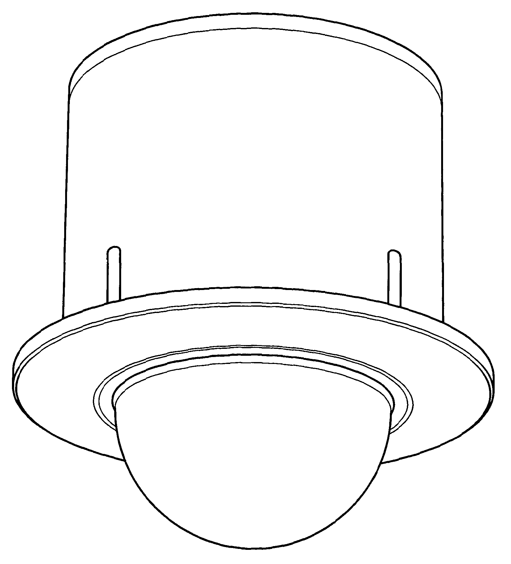
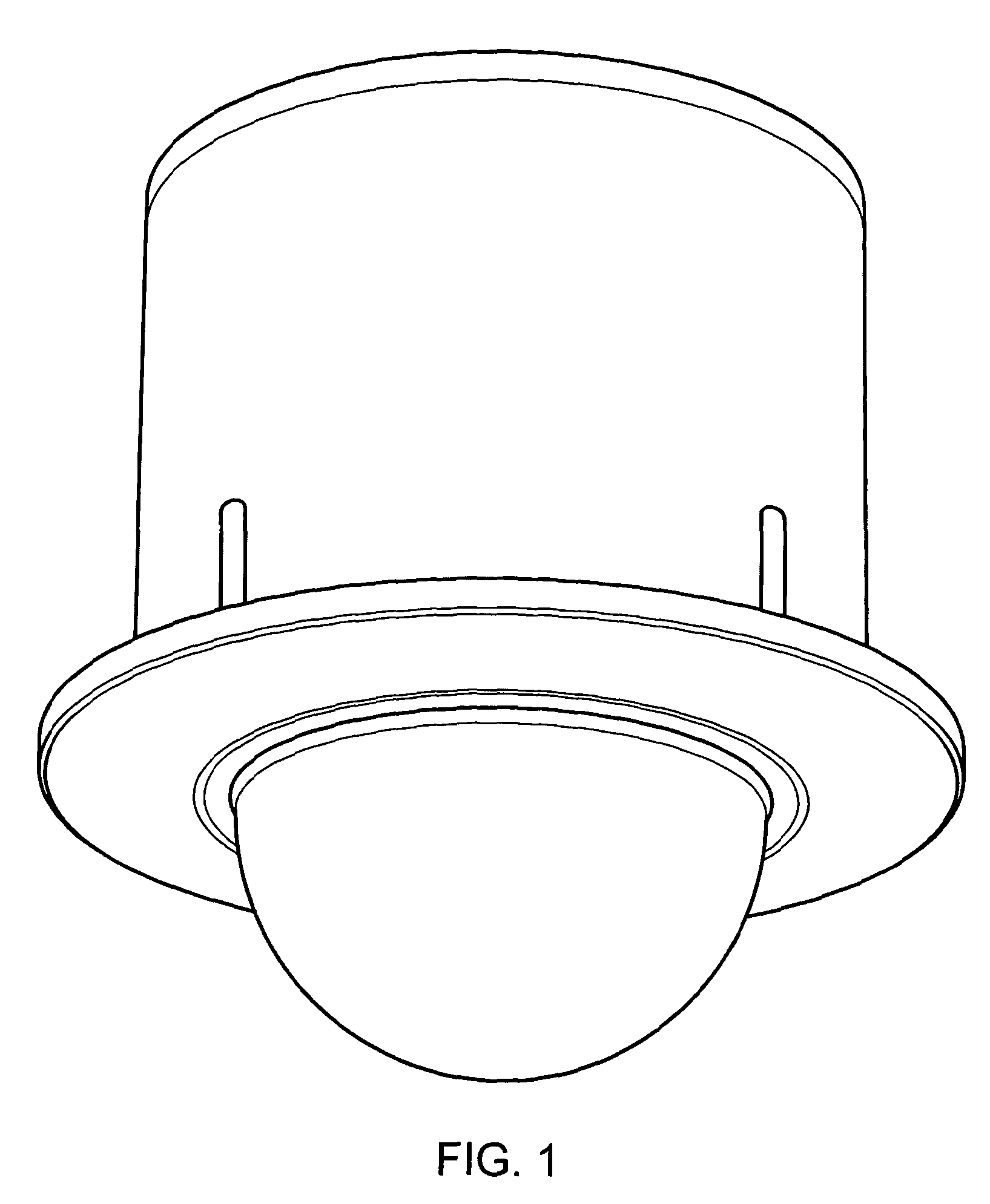
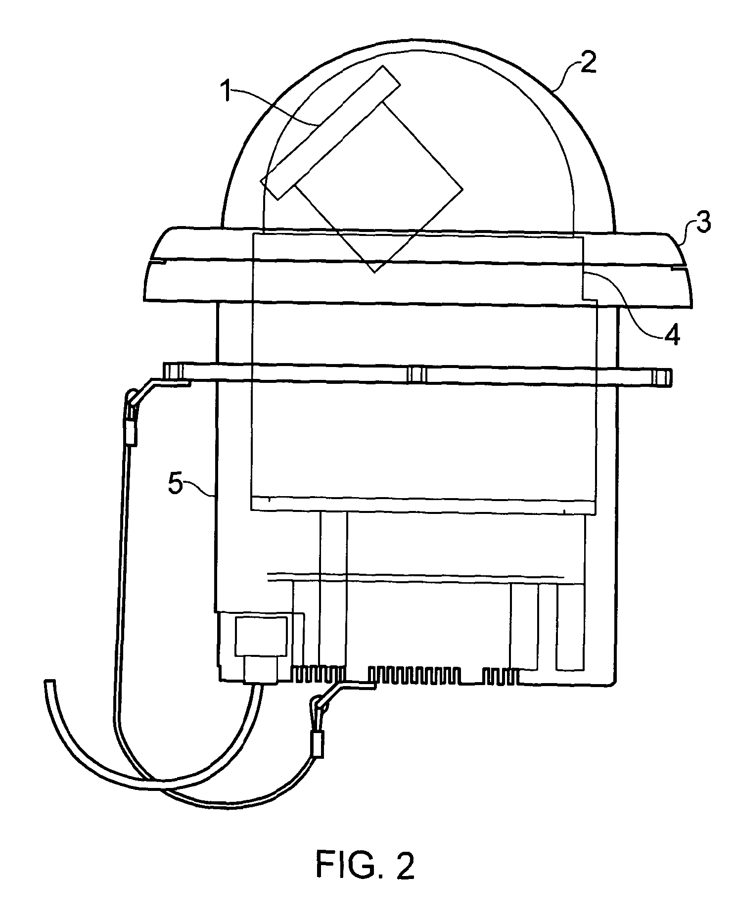
[0051]Referring to FIGS. 1 and 2, in which like parts bear the same reference numerals, generally there is shown a thermal imager 1, which is adapted for the marine environment, housed within a stainless steel housing 316 and behind an infra-red (IR) transmitting dome 2.

[0052]IR transmitting dome 2 encloses an hermetically sealed volume in which is housed the thermal imager 1 supported on a drivers, such a pan-tilt-zoom actuator (not shown).

[0053]The thermal imager 1 is supported on the pan-tilt-zoom actuator which itself is optionally supported on a gimbal (not shown) or another suitable stabilisation platform (not shown), operative under sensors (such as gyroscopes or solid state gyroscopes), so as to control the stability of the imager.

[0054]The imager, actuators, control devices, sensors and any stabilisation platforms are mounted on a base plate 7 that is connected to an interior of a generally right circular cylindrical shaped housing 5 formed from 316 stainless steel, which i...


PUM


Abstract

The present invention relates to an imaging device with a thermal imaging surveillance capability for safety, security and situational awareness. Closed circuit television systems (CCTV) are usually supported on drive and actuating mechanisms so that their active imaging portions are housed in a protective environment in a transparent dome. Existing thermal imaging devices are used in fixed configurations or on platforms and are bulky and expensive. In addition they are unsuitable for harsh marine environments. The invention is an imaging device and comprises: a thermal imager, which in use is housed within a sealed housing. A pan and tilt mechanism is supported in the housing for displacing the thermal imager. A dome, formed from an infra-red (IR) transmitting material, covers and seals the housing (which is ideally filled with an inert gas) thereby resulting in an arrangement that is resistant to exposure to water and salt and so provides an imager suitable for marine environments, as well resulting in an overall reduction in size of the imager compared with exposed pan and tilt mechanisms.

Description

BACKGROUND[0001]The present invention relates to an imaging device, a related system and method of fabrication. More particularly, but not exclusively, the invention relates to an imaging device with a thermal imaging surveillance capability.PRIOR ART[0002]Closed circuit television systems (CCTV) are usually supported on drive and actuating mechanisms so that their active imaging portions are housed in a protective environment. Conventionally CCTV cameras are housed within a transparent dome. The purpose of the dome is usually twofold in nature. Firstly, domes are tinted (so as to conceal the direction of the imager and to reduce glare); secondly the dome provides an environment which is sealed and protects lenses, actuators and drive equipment, from dirt, debris and moisture.[0003]Existing thermal imaging devices are used in fixed configurations or on platforms. The platforms are sometimes driveable by an actuating mechanism, so that the line of sight (LOS) of the imager can be var...

Claims


Application Information

Patent Timeline
IPC IPC(8): H04N5/33H04N7/18
CPCG08B13/19619G03B17/02G08B13/196H04N5/33H04N7/18H04N23/555H04N23/51
Inventor CHIVERS, BRIANCHANDLER, ANDREW CHRISTOPHERPARSONS, THOMAS JAMES
Owner CHIVERS BRIAN
Why Eureka
Try Eureka