
Circuit for converting a direct current voltage to an alternating current voltage

Inactive Publication Date: 2012-11-08
MOTECH INDUSTRIES
View PDF6 Cites 15 Cited by
  • Summary
  • Abstract
  • Description
  • Claims
  • Application Information

AI Technical Summary

Benefits of technology

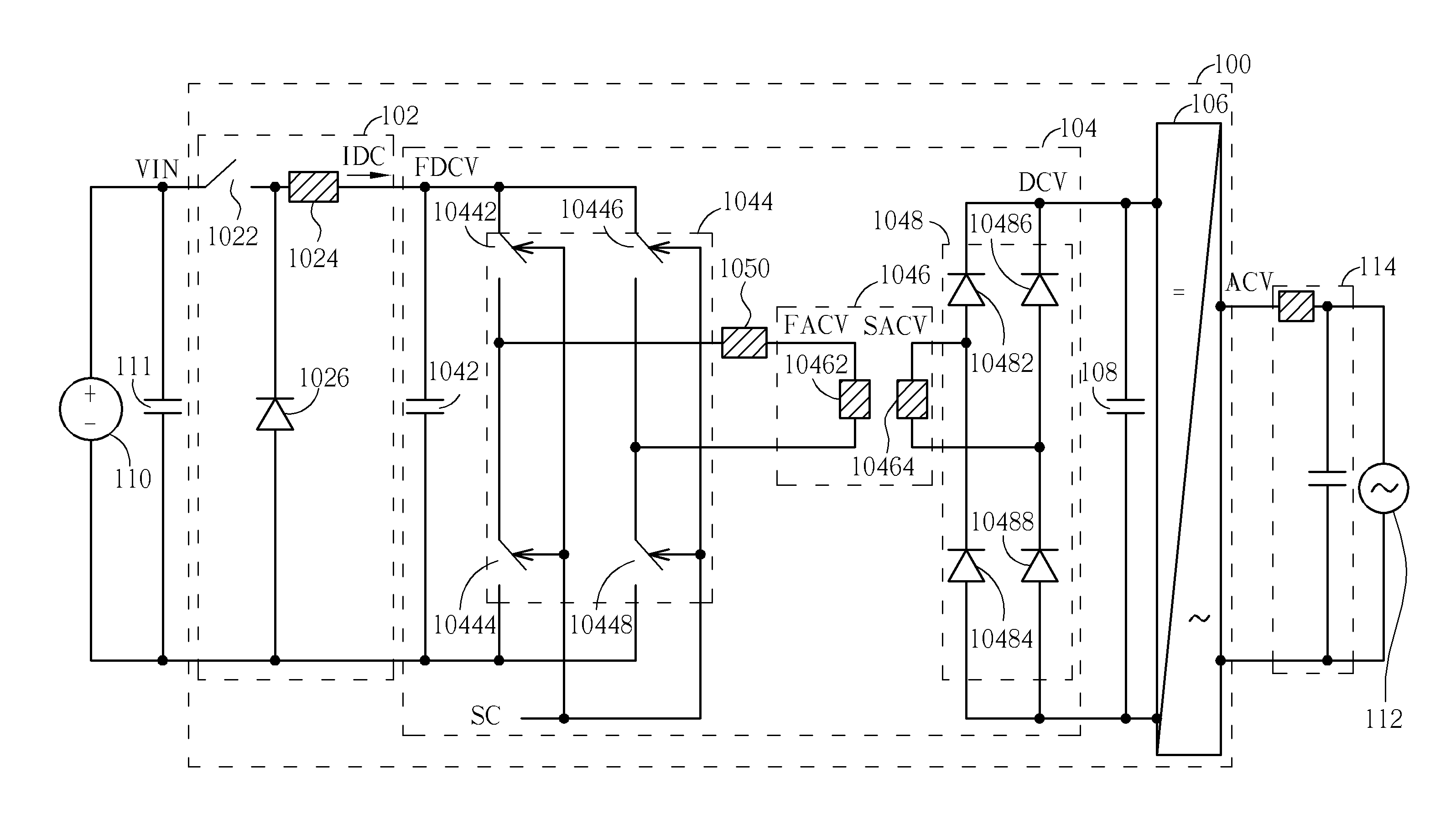
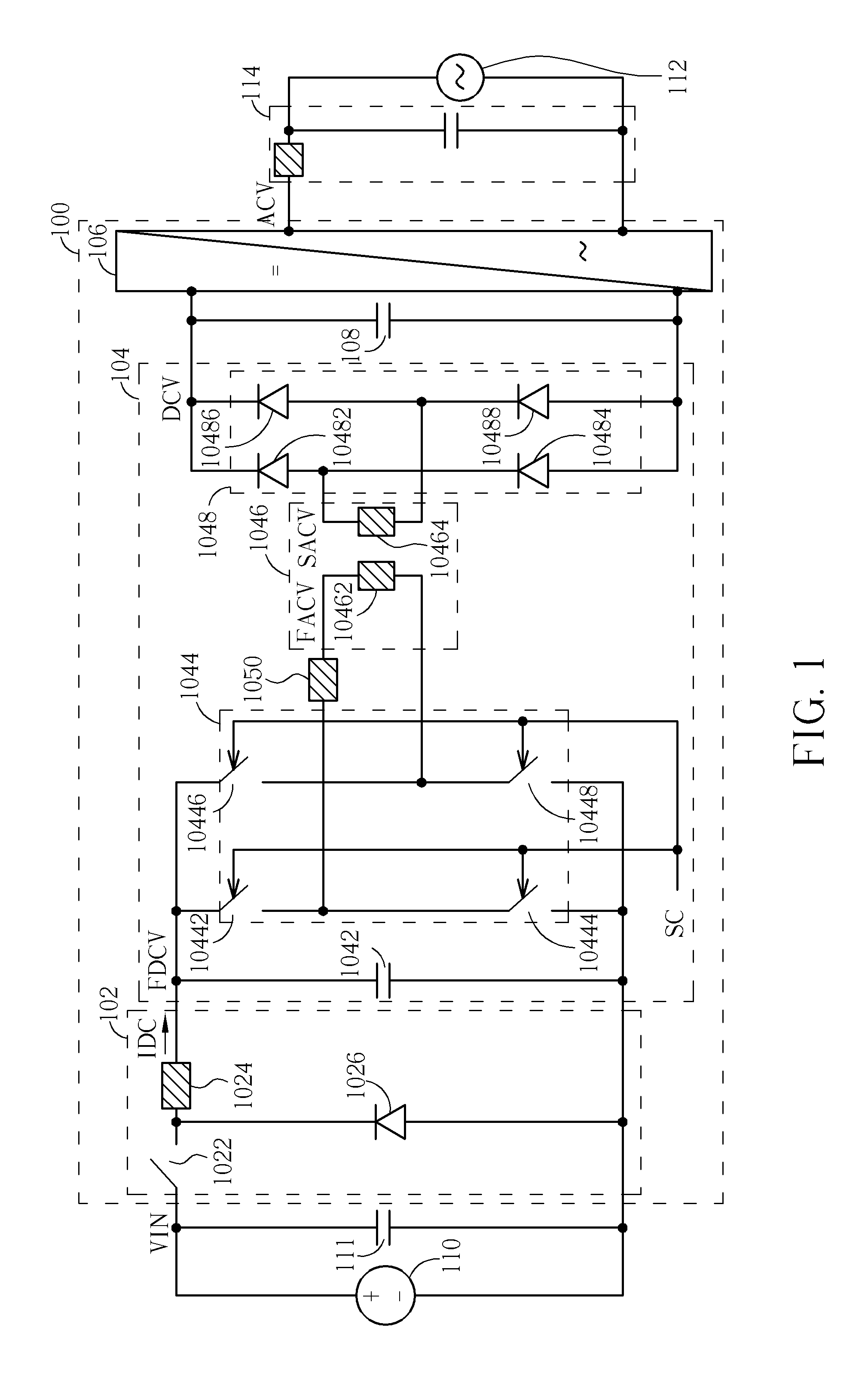
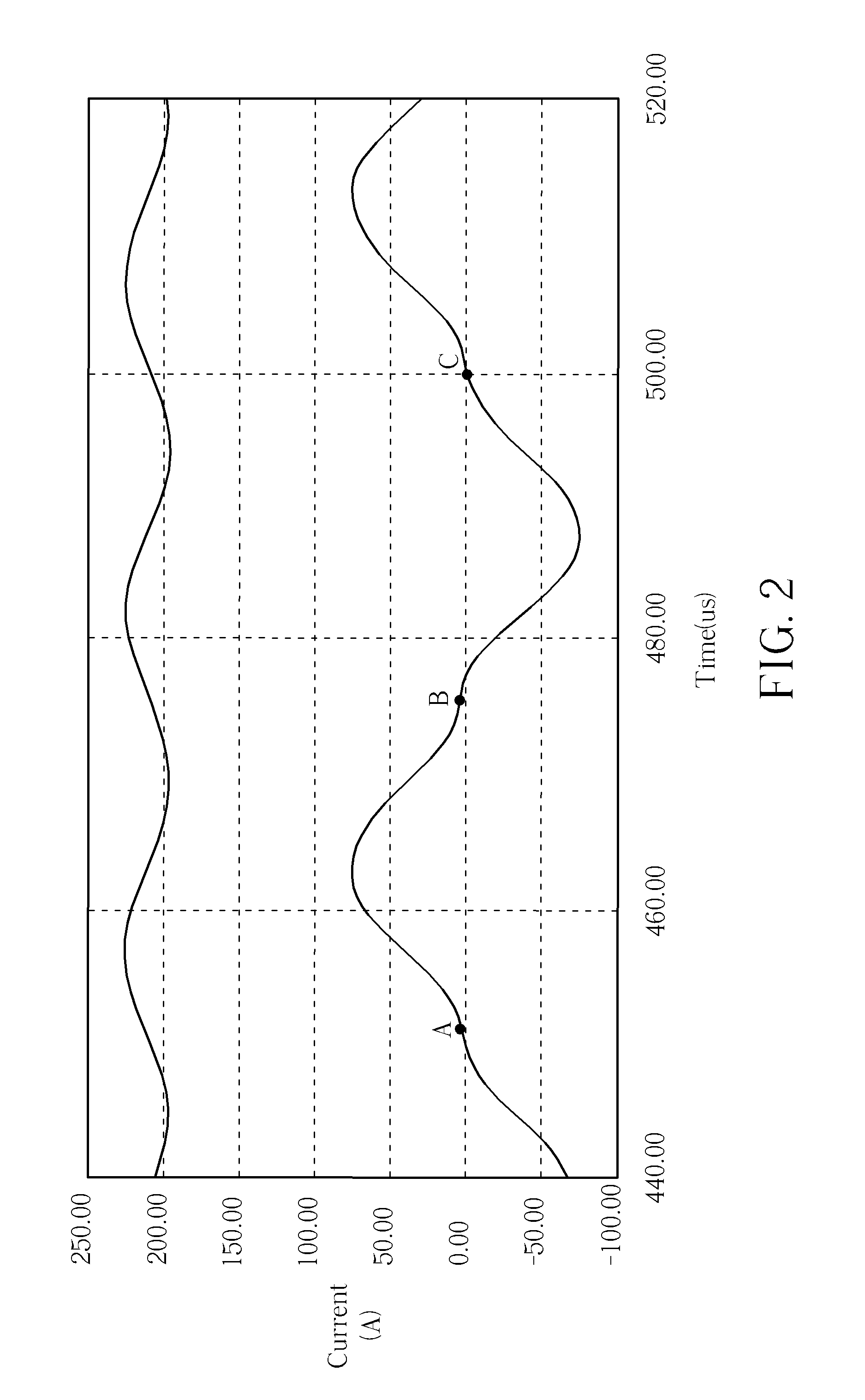
[0008]The present invention provides a circuit for converting a DC voltage into an AC voltage. The circuit utilizes a buck converter for a voltage source to operate at an optimal operation point, a high frequency transformer of a resonant DC voltage / DC voltage converter to fix a ratio of a first DC voltage to a DC voltage, and a DC voltage / AC voltage inverter to convert the DC voltage to an AC voltage and to output the AC voltage to an AC power supply network. In addition, a full bridge unit of the resonant DC voltage / DC voltage converter operates in a resonant mode with a resonant frequency, so switching loss of the full bridge unit can be reduced to a minimum value. That is to say, although the full bridge unit operates with the hard-switching mode, the full bridge unit has low switching loss characteristic of the soft-switching mode. In addition, the full bridge unit, the high frequency transformer, and a rectifier of the resonant DC voltage / DC voltage converter can provide a galvanic isolation function for isolating the voltage source from the AC power supply network. Therefore, the present invention not only has simpler design but also lower switching loss and higher conversion efficiency.

Problems solved by technology

However, switching loss of the power switches increases with power of the voltage source.
Therefore, when the circuit for converting the DC voltage into the AC voltage utilizes the hard-switching full bridge unit to convert the input voltage generated by the voltage source to the first AC voltage, the circuit for converting the DC voltage into the AC voltage has high switching loss.

Method used


Image

  • Circuit for converting a direct current voltage to an alternating current voltage
  • Circuit for converting a direct current voltage to an alternating current voltage
  • Circuit for converting a direct current voltage to an alternating current voltage

Examples


Embodiment Construction

[0013]Please refer to FIG. 1. FIG. 1 is a diagram illustrating a circuit 100 for converting a DC voltage into an AC voltage according to an embodiment. As shown in FIG. 1, the circuit 100 includes a buck converter 102, a resonant DC voltage / DC voltage converter 104, a DC voltage / AC voltage inverter 106, and a DC link capacitor 108. The buck converter 102 has a first terminal for coupling to a first terminal of a voltage source 110, a second terminal for coupling to a second terminal of the voltage source 110, and a third terminal for outputting a DC current IDC. A stabilization capacitor 111 is coupled between the first terminal and the second terminal of the voltage source 110 for stabilizing an input voltage VIN of the voltage source 110. The buck converter 102 is used for generating the DC current IDC according to the input voltage VIN of the voltage source 110 when the voltage source 110 operates at an optimal operation point, where the optimal operation point of the voltage sou...


PUM


Abstract

A circuit for converting a direct current voltage into an alternating current voltage includes a buck converter, a resonant DC voltage / DC voltage converter, a DC voltage / AC voltage inverter, and a DC link capacitor. The buck converter generates a DC current according to an input voltage generated by a voltage source operating at an optimal operation point. The resonant DC voltage / DC voltage converter converts the input voltage to a DC voltage according to a switch clock and a resonant frequency determined by a resonant capacitor and a resonant inductance of the resonant DC voltage / DC voltage converter. The DC voltage / AC voltage inverter converts the DC voltage and outputs an AC voltage to an AC power supply network. The DC link capacitor adjusts power outputted by the DC voltage / AC voltage converter to regulate the DC voltage.

Description

BACKGROUND OF THE INVENTION[0001]1. Field of the Invention[0002]The present invention is related to a circuit for converting a direct current (DC) voltage into an alternating current (AC) voltage, and particularly to a circuit for converting a DC voltage into an AC voltage that not only has simpler design but also lower switching loss and higher conversion efficiency.[0003]2. Description of the Prior Art[0004]Due to technical requirements and different country-specific rules, a voltage source needs a circuit for converting a DC voltage into an AC voltage to transfer energy of the voltage source to an AC power supply network, and to isolate the voltage source from the AC power supply network.[0005]The circuit for converting the DC voltage into the AC voltage utilizes a buck converter to cope with a large range of variation in an output voltage of the voltage source, and for the voltage source to operate at a maximum power point. When the voltage source operates at the maximum power p...

Claims


Application Information

Patent Timeline
IPC IPC(8): H02J3/36
CPCH02M7/48H02M2007/4811H02M2001/007H02M1/007H02M7/4811
Inventor LIU, YUNG-HSIANGCHU, KUO-HSINWANG, YU-KAINIU, YUAN-CHAO
Owner MOTECH INDUSTRIES
Learn More