Complexity change detection for video transmission system

a technology of video transmission system and complexity change, applied in the field of video transmission system complexity change detection, can solve problems such as complexity change, and achieve the effect of detecting and minimizing degradation or possible latency and bit rate impacts, and minimizing quality degradation

Inactive Publication Date: 2012-11-08
CAVIUM NETWORKS
View PDF7 Cites 10 Cited by
  • Summary
  • Abstract
  • Description
  • Claims
  • Application Information

AI Technical Summary

Benefits of technology

[0010]Embodiments of the present invention disclose a complexity change detection process for a video transmission system that detects and minimizes the quality degradation due to the presence of complexity changes in predicting video images while not severely impacting the rate control for the system. The system detects and minimizes the degradation or possible latency and bit rate impacts by using different processes for the type of frames being transmitted in the system.

Problems solved by technology

If the compression level deviates from the previous level, then a complexity change may have occurred.

Method used


Image

  • Complexity change detection for video transmission system
  • Complexity change detection for video transmission system
  • Complexity change detection for video transmission system

Examples


Embodiment Construction

[0022]Aspects of the invention are disclosed in the accompanying description. Alternate embodiments of the present invention and their equivalents are devised without parting from the spirit or scope of the present invention. It should be noted that like elements disclosed below are indicated by like reference numbers in the drawings.

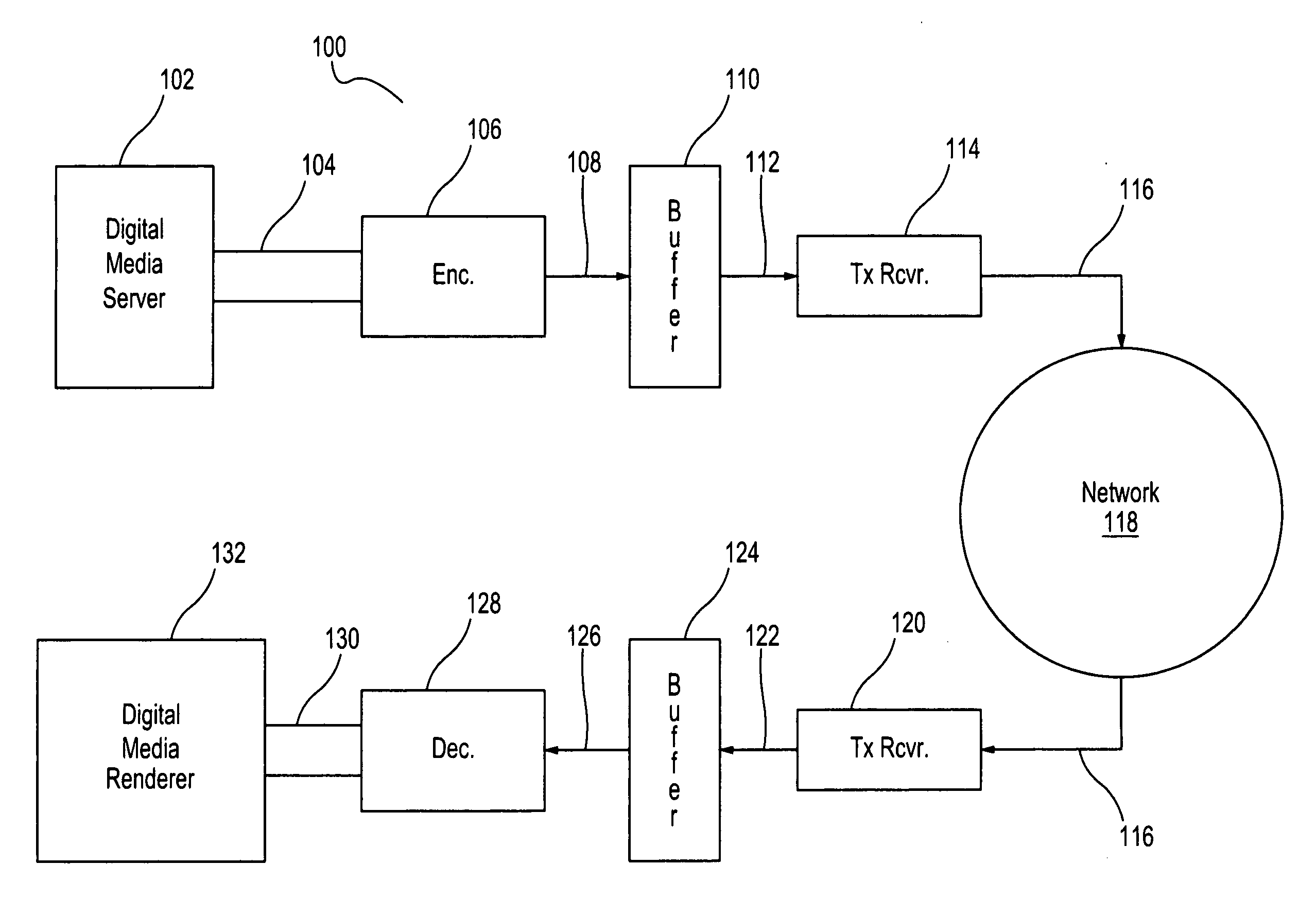
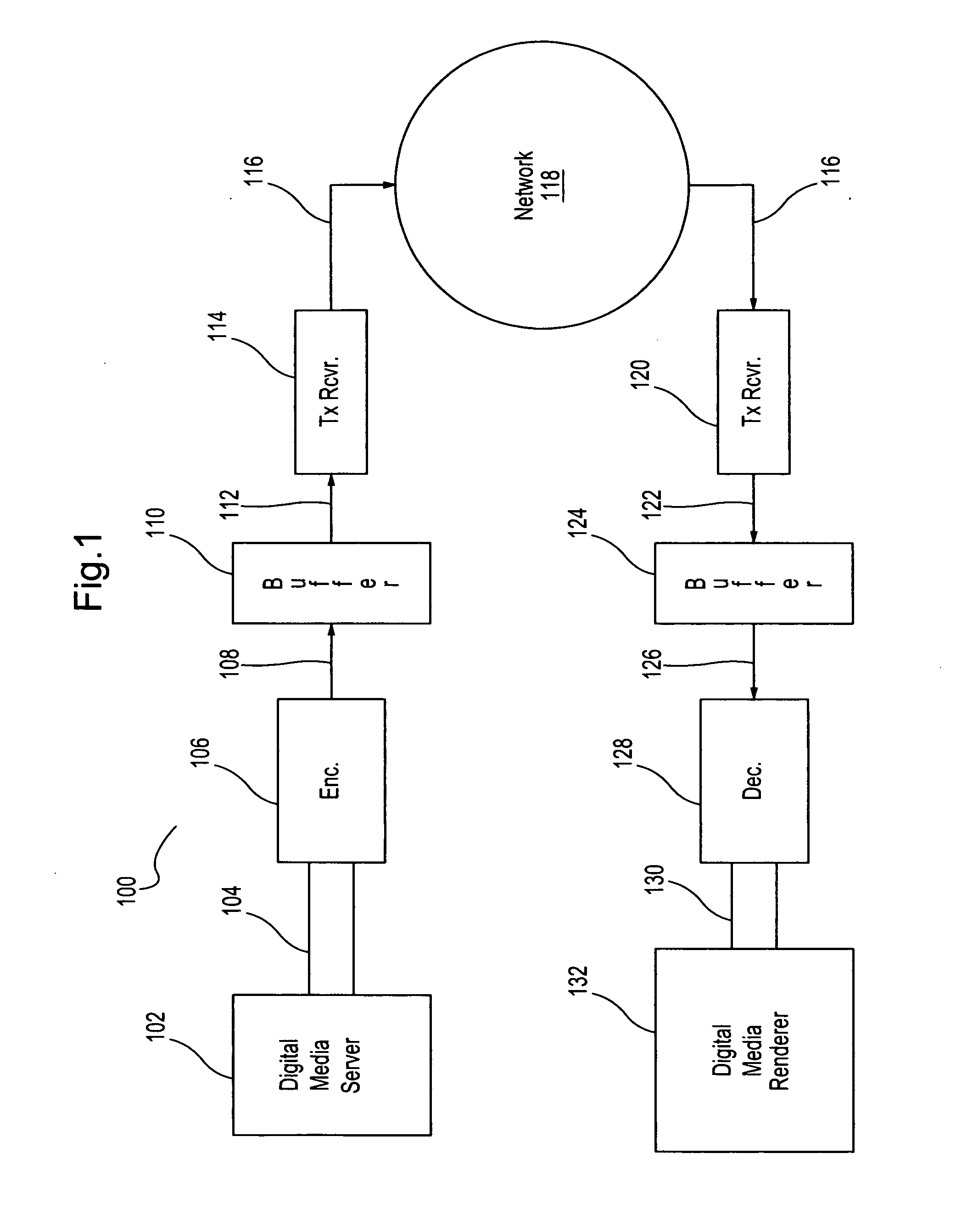
[0023]FIG. 1 depicts a system 100 for transmitting and receiving video signal data according to the disclosed embodiments. System 100 may be any system or collection of devices that connect over a network to share information. System 100, for example, may be a gaming system where video content is generated in the gaming console and then transmitted to a high-definition digital media renderer, such as a flat-screen television. Alternatively, system 100 may be a security monitoring system using high definition (HD) video.

[0024]Digital media server 102 generates the video content to be transmitted. Digital media server 102 may be any device, console, camer...


PUM


Abstract

A video transmission system includes an encoder and a decoder. As video data is encoded, the system uses temporal or spatial prediction to reduce the number of bits needed to encode frames. An increase in the complexity of the data results when motion vectors or patterns occurs. The complexity change is detected for intra-frame and inter-frame frames by monitoring statistics and motion estimation information for the macroblocks within the current frame. Once the complexity change is detected, the encoder or the system takes actions to prevent latency, bit rate fluctuation or quality degradation for the video transmission.

Description

FIELD OF THE INVENTION[0001]The present invention relates to transferring video signals over a network. More particularly, the present invention relates to detecting a complexity change within the video signal transmission to minimize possible quality degradation or latency issues due to the system constraints.DISCUSSION OF THE RELATED ART[0002]Before transmitting video content over a network, a video frame is compressed using an algorithm to encode the data. Some of these algorithms may be complex and the amount of data significant. For a defined video compression system, the necessary bit rate to achieve a specific video quality may depend on the complexity of the image being encoded. Complex images may require a higher bit rate for encoding.[0003]To reduce the amount of data to encode, known video transmission systems may use prediction processes to re-use parts of an image already available. Known systems may use temporal prediction or spatial prediction to reduce the data rate ...

Claims


Application Information

Patent Timeline
Patent Type & Authority Applications(United States)
IPC IPC(8): H04N7/26
CPCH04N19/139H04N19/159H04N19/152H04N19/124H04N19/176
Inventor RONCERO IZQUIERDO, FRANCISCO J.DUENAS, ALBERTO
Owner CAVIUM NETWORKS
Why Eureka
Try Eureka