Desorption of a Desiccant By Radio Waves or Microwaves For a Downhole Sorption Cooler

a technology of radio waves or microwaves and sorption coolers, which is applied in the direction of borehole/well accessories, insulation, refrigeration machines, etc., can solve the problems of limited use of these methods and the end of the cooling operation

Active Publication Date: 2012-11-15
BAKER HUGHES INC
View PDF7 Cites 12 Cited by
  • Summary
  • Abstract
  • Description
  • Claims
  • Application Information

AI Technical Summary

Problems solved by technology

However, once the desiccant becomes saturated with refrigerant, the cooling operation ends.
However, due to temperatures and

Method used


Image

  • Desorption of a Desiccant By Radio Waves or Microwaves For a Downhole Sorption Cooler
  • Desorption of a Desiccant By Radio Waves or Microwaves For a Downhole Sorption Cooler
  • Desorption of a Desiccant By Radio Waves or Microwaves For a Downhole Sorption Cooler

Examples


Embodiment Construction

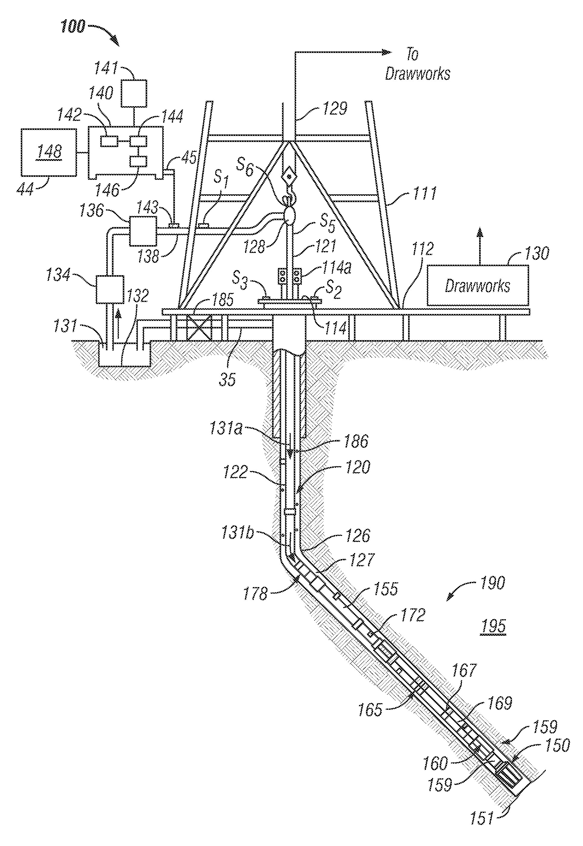
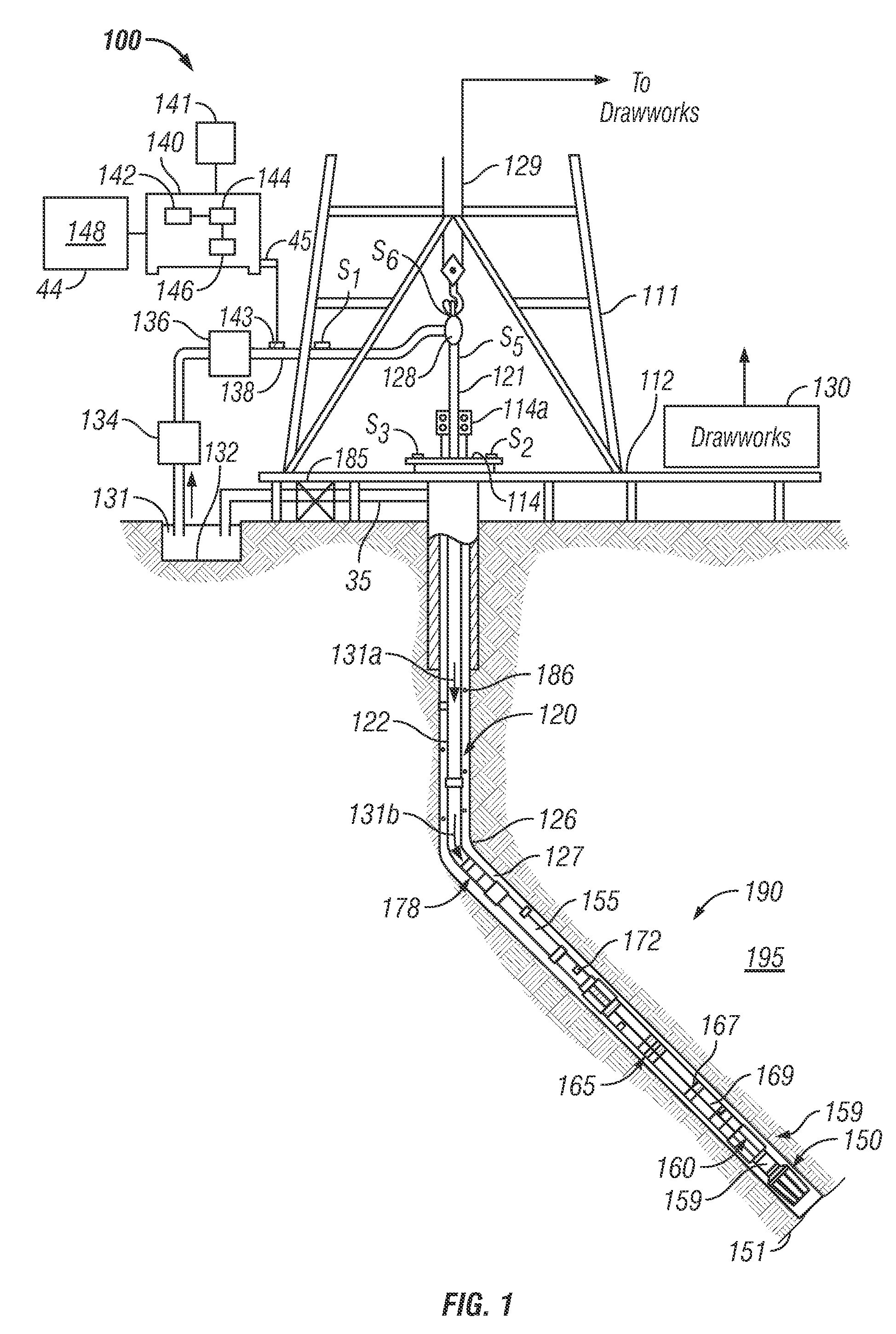
[0011]FIG. 1 is a schematic diagram of an exemplary drilling system 100 for drilling a wellbore using an apparatus that can be operated according to the exemplary methods disclosed herein. Exemplary drilling system 100 includes a drill string 120 that includes a drilling assembly or bottomhole assembly (“BHA”) 190 conveyed in a wellbore 126. The drilling system 100 includes a conventional derrick 111 erected on a platform or floor 112 which supports a rotary table 114 that is rotated by a prime mover, such as an electric motor (not shown), at a desired rotational speed. A tubing (such as jointed drill pipe) 122 having the drilling assembly 190 attached at its bottom end extends from the surface to the bottom 151 of the wellbore 126. A drill bit 150, attached to drilling assembly 190, disintegrates the geological formations when it is rotated to drill the wellbore 126. The drill string 120 is coupled to a drawworks 130 via a Kelly joint 121, swivel 128 and line 129 through a pulley. ...


PUM


Abstract

A method, apparatus and system for cooling a component of a downhole tool is disclosed. The apparatus includes a first desiccant configured to adsorb a refrigerant gas. A transmitter is configured to transmit electromagnetic energy into the first desiccant to enable desorption of the refrigerant gas from the first desiccant. A condenser condenses the desorbed refrigerant gas into a liquid phase. The condensed refrigerant evaporates from a liquid phase to a gaseous phase to cool the component. A second desiccant can be used, wherein the processor is configured to operate the cooling system in a first mode of operation in which the first desiccant is in thermal communication with the component and the second desiccant is thermally isolated from the component and a second mode of operation in which the second desiccant is in thermal communication with the component and the first desiccant is thermally isolated from the component.

Description

BACKGROUND OF THE DISCLOSURE[0001]The present disclosure is related to sorption cooling of a component of a downhole tool. One way to cool a device downhole includes evaporating a refrigerant stored on the downhole tool from a liquid phase to a gaseous phase. Once the evaporated refrigerant has cooled the component, it is generally stored at a desiccant or other solid body which adsorbs the gas-phase refrigerant in the downhole tool until the tool is retrieved to the surface, at which time the refrigerant is removed and / or the refrigerant is desorbed from the desiccant by thermal heating. However, once the desiccant becomes saturated with refrigerant, the cooling operation ends. It is generally time-efficient and cost-efficient to regenerate the desiccant downhole by desorbing the evaporated refrigerant from the desiccant downhole rather than bringing the downhole tool to the surface. Known methods of desiccant regeneration include heating of the desiccant, reducing pressure within ...

Claims


Application Information

Patent Timeline
IPC IPC(8): F25B21/00F25B17/00
CPCE21B36/001
Inventor PENNEWITZ, ERIKKRUSPE, THOMASJUNG, SEBASTIAN
Owner BAKER HUGHES INC
Why Eureka
Try Eureka