
Sound baffling cooling system for LED thermal management and associated methods

a cooling system and led thermal management technology, applied in semiconductor devices, semiconductor/solid-state device details, lighting and heating apparatus, etc., can solve the problems of increasing the power requirements of semiconductor based electronic systems, generating heat, and generating heat, so as to achieve increased operational capacity, convenient use, and convenient use

Inactive Publication Date: 2012-11-15
LIGHTING SCI GROUP
View PDF15 Cites 24 Cited by
  • Summary
  • Abstract
  • Description
  • Claims
  • Application Information

AI Technical Summary

Benefits of technology

[0007]The cooling system of the present invention may provide thermal management of semiconductor devices, advantageously keeping LED junction temperatures within acceptable operating levels while maintaining a compact form factor. Additionally, the cooling system of the present invention may advantageously allow a connected semiconductor device to operate at an elevated electrical current, providing additional operational capacity, i.e. brightness, from a smaller semiconductor package. Furthermore, through the effective cooling provided by the cooling system of the present invention, a connected electronic semiconductor device may beneficially have an increased operational life due to decreased thermal stress that may damage the connected semiconductor.

Problems solved by technology

As electronic devices operate, they may generate heat.
However, in applications wherein a higher current is passed through a semiconductor, the heat generated through operation of the semiconductor may be greater than its capacity to dissipate such heat.
However, increasing power requirements of semiconductor based electronic systems may still produce more heat than may be capably dissipated from a connected heatsink.
Furthermore, continued enlargement of the heatsink size may not be practical for some applications.
The rapid development of high density power light emitting diode (LED) bulbs has created a challenge regarding effective thermal management.
As a result, the heat generated from the operation of high density power LEDs is quickly exceeding the dissipation capacity of traditional passive heatsinks to keep transistor junctions below maximum operating temperatures while remaining compact in size.

Method used


Image

  • Sound baffling cooling system for LED thermal management and associated methods
  • Sound baffling cooling system for LED thermal management and associated methods
  • Sound baffling cooling system for LED thermal management and associated methods

Examples


Embodiment Construction

[0032]The present invention will now be described more fully hereinafter with reference to the accompanying drawings, in which preferred embodiments of the invention are shown. This invention may, however, be embodied in many different forms and should not be construed as limited to the embodiments set forth herein. Rather, these embodiments are provided so that this disclosure will be thorough and complete, and will fully convey the scope of the invention to those skilled in the art. Those of ordinary skill in the art realize that the following descriptions of the embodiments of the present invention are illustrative and are not intended to be limiting in any way. Other embodiments of the present invention will readily suggest themselves to such skilled persons having the benefit of this disclosure. Like numbers refer to like elements throughout.

[0033]In this detailed description of the present invention, a person skilled in the art should note that directional terms, such as “abov...


PUM


Abstract

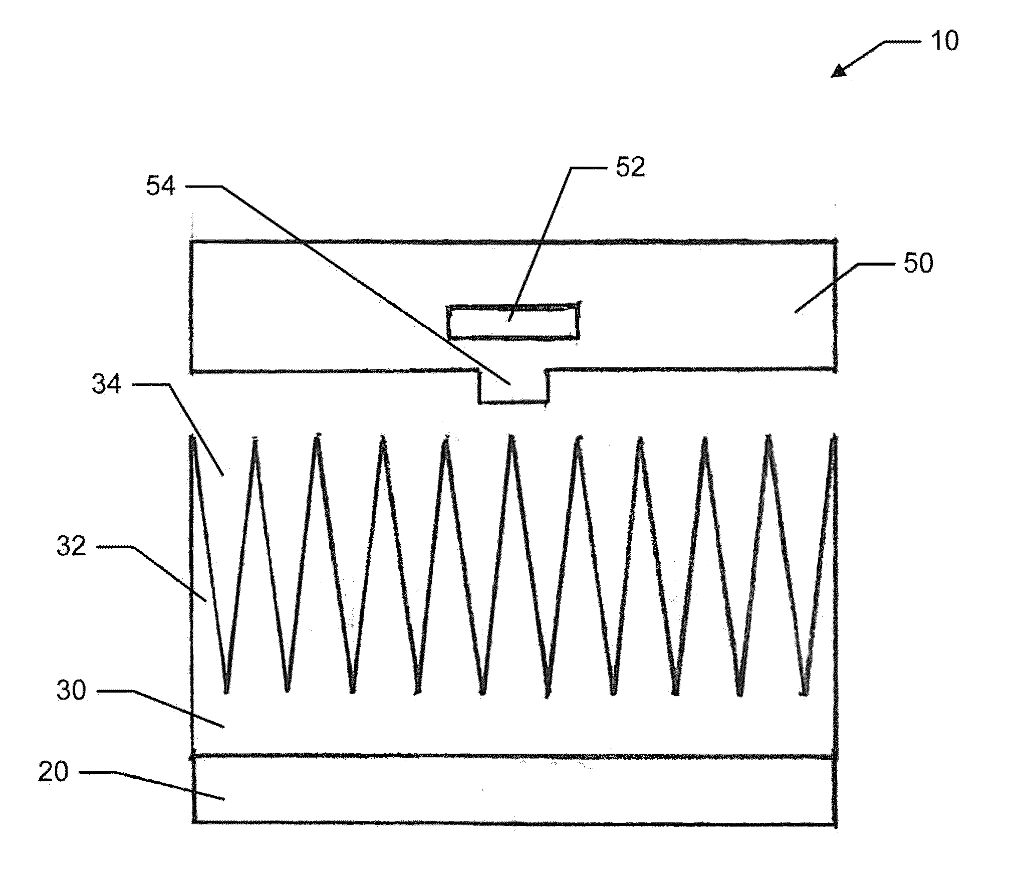
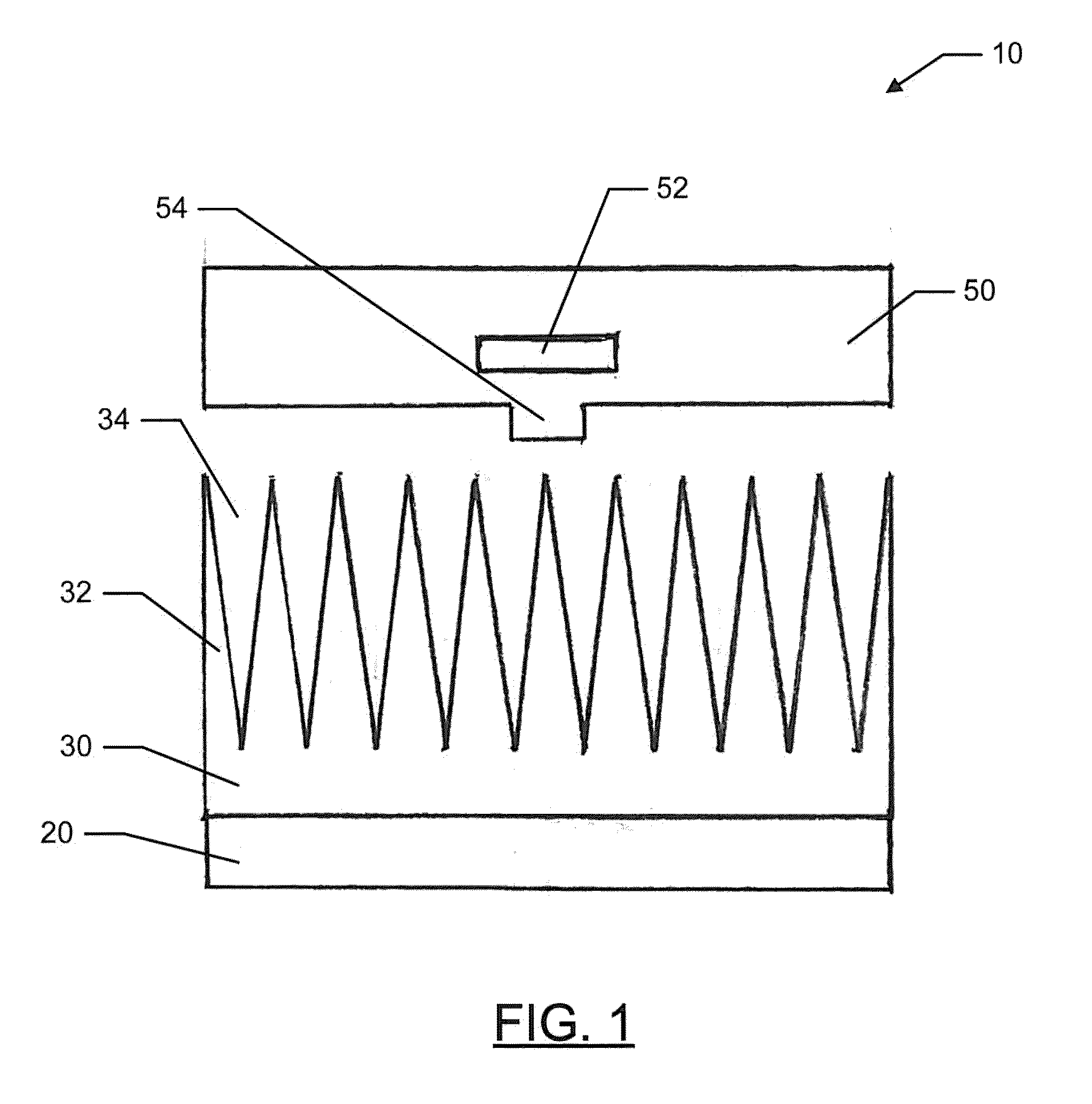
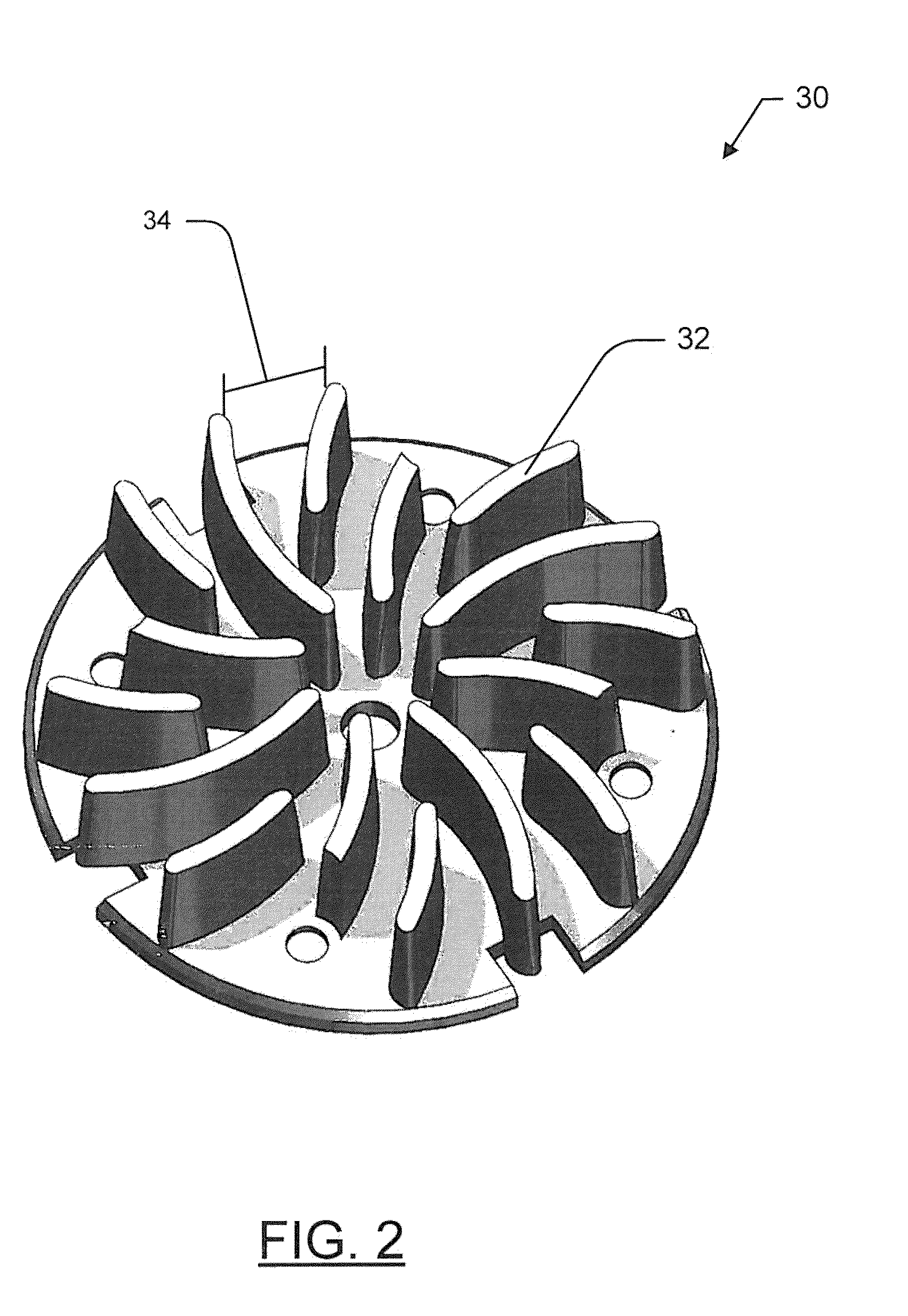
A cooling system for light emitting diodes (LEDs) is provided that may comprise acoustic baffle members, a micro-channel heatsink that includes fins adjacent to the LEDs, and a fluid flow generator adjacent to the micro-channel heatsink that directs a fluid in a flow direction. The fluid flow generator may include an input to receive the fluid and an exit to exhaust the fluid, which may contact a surface area of the fins. The sound emitted by the fluid flow generator may be substantially cancelled by the acoustic baffle members, which may reflect the sound to a source location as reflected sound waves defined by a substantially inverted phase.

Description

FIELD OF THE INVENTION[0001]The present invention relates to the field of lighting devices and, more specifically, to active cooling systems for lighting devices that direct a fluid across fins of a heatsink.BACKGROUND OF THE INVENTION[0002]As electronic devices operate, they may generate heat. This especially holds true with electronic devices that involve passing an electrical current through a semiconductor. As the amount of current passed through the electronic device may increase, so may the heat generated from the current flow.[0003]In a semiconductor device, if the heat generated from the device is relatively small, i.e. the current passed through the semiconductor is low, the generated heat may be effectively dissipated from the surface area provided by the semiconductor device. However, in applications wherein a higher current is passed through a semiconductor, the heat generated through operation of the semiconductor may be greater than its capacity to dissipate such heat....

Claims


Application Information

Patent Timeline
Patent Type & Authority Applications(United States)
IPC IPC(8): H01L23/467
CPCH01L23/467H01L33/642H01L33/648H01L2924/0002H01L2924/00
Inventor MAXIK, FREDRIC S.SOLER, ROBERT R.BARTINE, DAVID E.ZHOU, RANBASTIEN, VALERIE A.
Owner LIGHTING SCI GROUP
Learn More