
Electrical power system

a technology of electric power system and power distribution network, which is applied in the integration of power network operation system, electrical apparatus, information technology support system, etc., can solve the problems of limited power supply capacity of electricity distribution network of building to hoisting machines of elevators, etc., to improve the dependability and operational reliability of electricity distribution network, and improve the capacity of electricity distribution network.

Active Publication Date: 2012-11-15
KONE CORP
View PDF13 Cites 9 Cited by
  • Summary
  • Abstract
  • Description
  • Claims
  • Application Information

AI Technical Summary

Benefits of technology

[0006]When connecting a number of high-powered elevators to the electricity distribution network of a building, the capacity of the electricity distribution network of the building may run out if a number of elevators are used simultaneously during the acceleration phase of the heavy direction, or if a number of elevators are used simultaneously during the deceleration phase of the light direction. In other words, when examining high-powered elevator systems connected to an electricity distribution network of a building, it has been discovered that there is a special need to further develop the electrical power systems, on the one hand, for better utilizing the capacity of the electricity distribution network of the building and the capacity of the elevator system and also, on the other hand, for improving the dependability and operational reliability of the electricity distribution network of the building and of the elevator system.
[0013]In some embodiments of the invention the temporary storage of energy belonging to the first power supply device is arranged to receive the part of the power flowing from a hoisting machine of an elevator to a second power supply device, and also to surrender the part of the power flowing from the second power supply device to a hoisting machine of an elevator. In this case the part of the electrical power flowing between a hoisting machine of an elevator and the second power supply device can be temporarily stored in the temporary storage of energy belonging to the first power supply device by surrendering as well as by receiving the power flowing between the second power supply device and the electricity distribution network of the building via the electricity distribution network of the building with the first power supply device, which reduces the power flow between the public electricity network and the electricity distribution network of the building. The power supply between the electricity distribution network of the building and the power supply devices preferably occurs also in this embodiment of the invention preferably with the network inverter rectifier of each power supply device.

Problems solved by technology

On the other hand, the power to be supplied via the electricity distribution network of the building to the hoisting machines of an elevator can also be limited e.g. by supplying a part of the power requirement of the hoisting machines of the elevator from temporary storages of energy fitted in connection with the power supply system.

Method used


Image

  • Electrical power system
  • Electrical power system
  • Electrical power system

Examples


embodiment 1

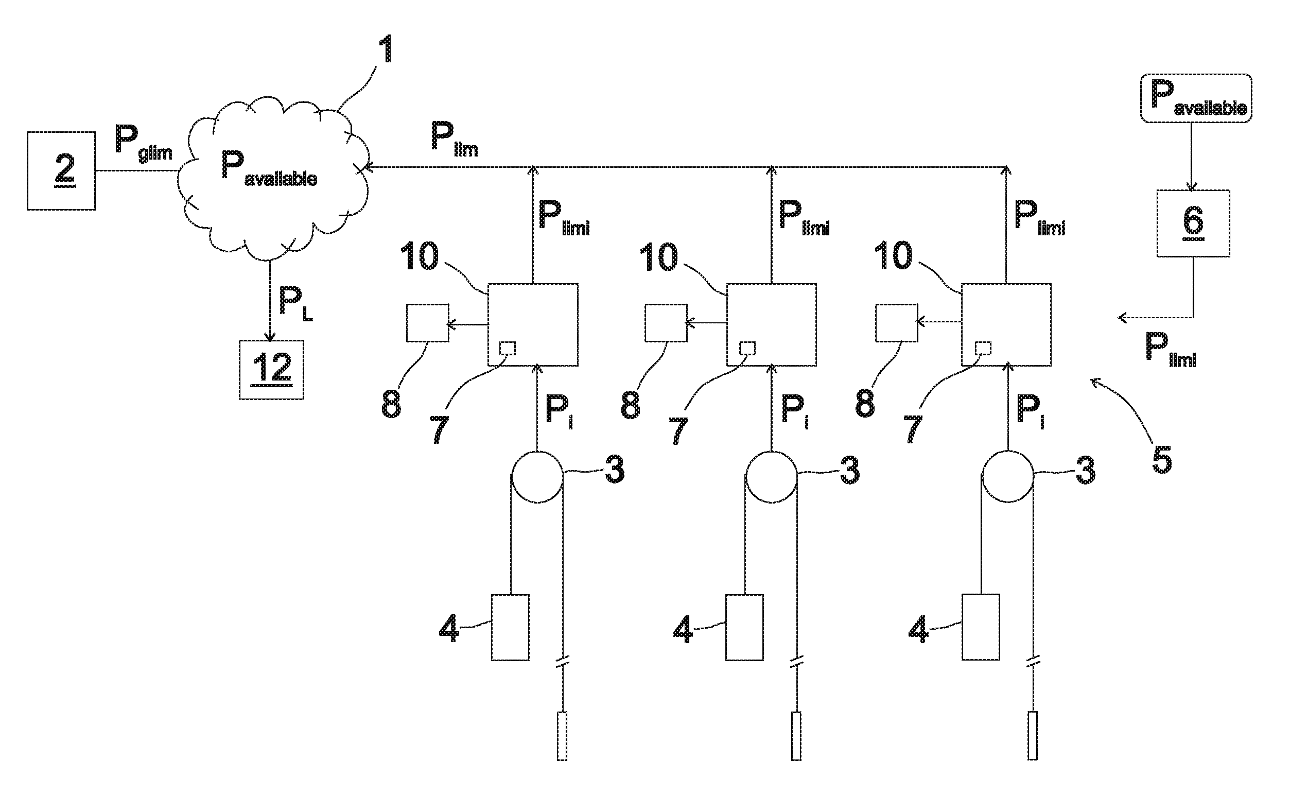
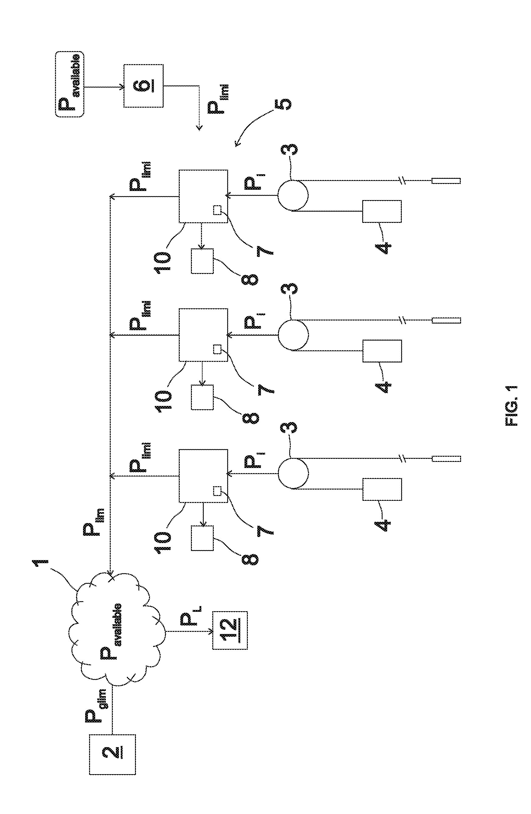
[0023]The electrical power system presented in FIG. 1 comprises a number of high-powered elevators. In each of the elevators an elevator car 4 and a counterweight are suspended in the elevator hoistway with elevator ropes, a belt, or corresponding, passing via the traction sheave of the hoisting machine 3 of an elevator. The elevator car 4 is moved with the hoisting machine 4 of the elevator. An induction motor or synchronous motor, for example, such as a permanent-magnet synchronous motor, in which rotor excitation is implemented with permanent magnets, can be used as the power-producing part of the hoisting machine. The power supply to the aforementioned power-producing part of the hoisting machine 3 of the elevator occurs with frequency converters 10 from the electricity distribution network 1 of the building. Each frequency converter comprises an interface to the hoisting machine 3 of the elevator and to the electricity distribution network 1 of the building. The frequency conve...

embodiment 2

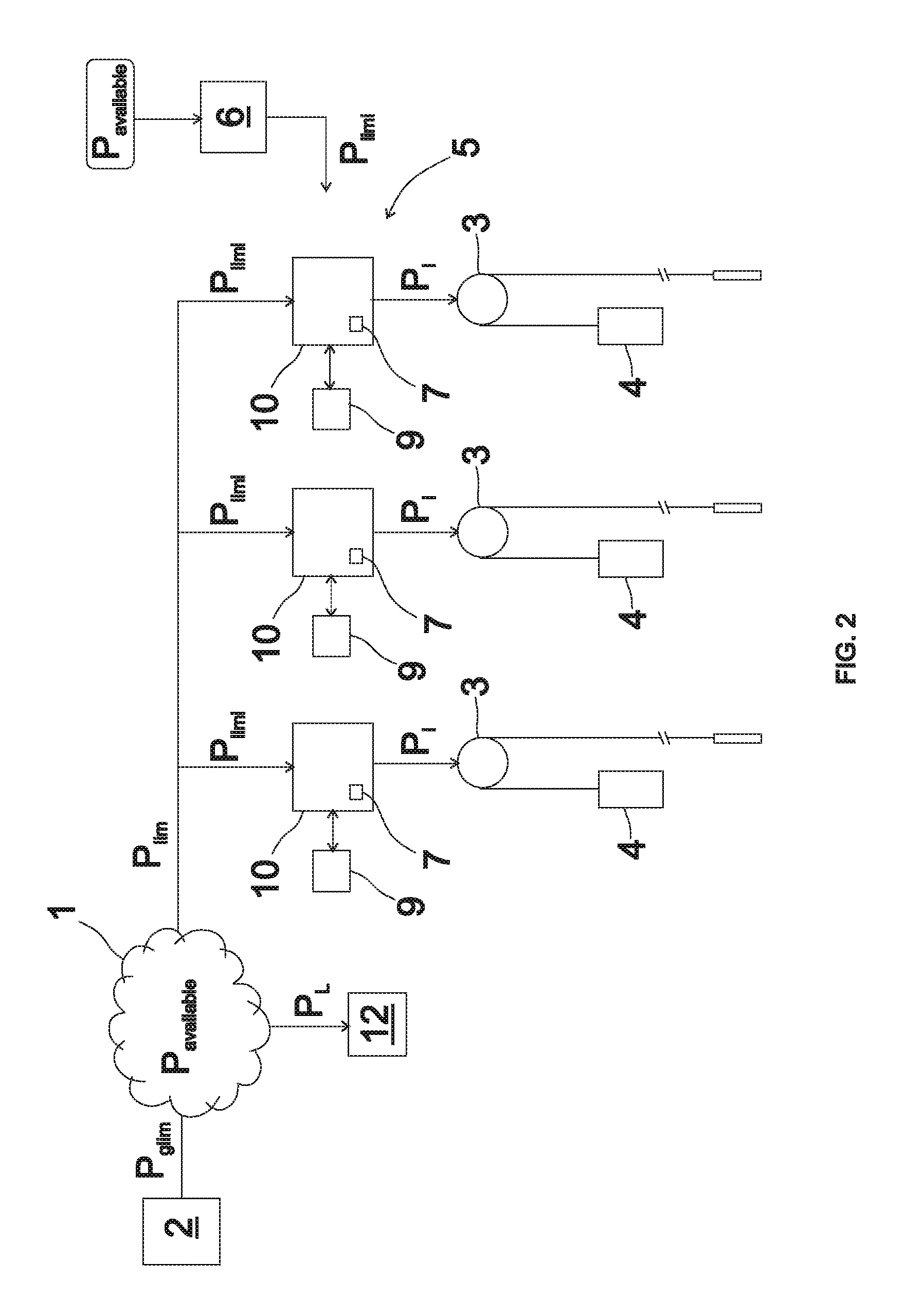
[0037]The electrical power system presented in FIG. 2 comprises a number of high-powered elevators. In each of the elevators an elevator car 4 and a counterweight are suspended in the elevator hoistway with elevator ropes, a belt or corresponding passing via the traction sheave of the hoisting machine 3 of the elevator. The elevator car 4 is moved with the hoisting machine 4 of the elevator. An induction motor or synchronous motor, for example, such as a permanent-magnet synchronous motor in which rotor excitation is implemented with permanent magnets, can be used as the power-producing part of the hoisting machine. The power supply to the aforementioned power-producing part of the hoisting machine 3 of the elevator occurs with frequency converters 10 from the electricity distribution network 1 of the building. Each frequency converter comprises an interface to the hoisting machine 3 of the elevator and to the electricity distribution network 1 of the building. The frequency convert...


PUM


Abstract

The invention relates to an electrical power system for operating elevators. The electrical power system comprises: an electricity distribution network of a building, which comprises an interface to a public electricity network; a plurality of hoisting machines of an elevator, each of which hoisting machines of an elevator is equipped to move an elevator car in an elevator hoistway; and also a power supply system, which comprises an interface to the aforementioned hoisting machines of the elevator, and which power supply system comprises an interface to the electricity distribution network of the building, for supplying power between the hoisting machines of the elevator and the electricity distribution network of the building.

Description

CROSS-REFERENCE TO RELATED APPLICATIONS[0001]This is a Continuation of PCT / FI2011 / 050043 filed on Jan. 21, 2011, which is an International Application claiming priority from FI 20105129 filed on Feb. 10, 2010; the entire contents of each of which are hereby incorporated by reference.FIELD OF THE INVENTION[0002]The invention relates to electrical power systems, more particularly in connection with elevators.BACKGROUND OF THE INVENTION[0003]An elevator car is moved in the elevator hoistway e.g. with suspension ropes traveling via the traction sheave of the hoisting machine of the elevator. When the elevator runs in the heavy direction, the force effect of the hoisting machine of the elevator is parallel with the direction of movement of the suspension ropes of the elevator car that travel on the traction sheave. In this case the hoisting machine of the elevator receives electrical power from the electricity network, e.g. through a frequency converter. When the elevator runs in the lig...

Claims


Application Information

Patent Timeline
IPC IPC(8): B66B1/50
CPCH02J3/14B66B1/302Y04S20/222Y02B70/3225H02J2310/12H02J2310/58B66B1/00H02J15/00
Inventor HARKONEN, ARIKALLIONIEMI, ANTTI
Owner KONE CORP
Learn More