
Brake pad wear indicator

a technology of wear indicator and brake pad, which is applied in the direction of friction lining, mechanical equipment, manufacturing tools, etc., can solve the problems of difficult or dangerous stopping of vehicles, large wear on the brake pad, and the sensor has so far proved unreliabl

Inactive Publication Date: 2012-11-15
MCGEE ROBERT
View PDF16 Cites 7 Cited by
  • Summary
  • Abstract
  • Description
  • Claims
  • Application Information

AI Technical Summary

Benefits of technology

The patent describes a brake pad that can visually indicate when it needs to be changed. The pad includes a layer that creates friction with the brakes and a layer that includes a dye that creates a visible dust on the brakes. This allows for easier maintenance and replacement of the brake pad. The patent also describes a system for braking a wheeled vehicle that includes the brake pad and a brake caliper. The method of manufacturing the brake pad is also provided. The technical effects of this patent are improved efficiency and convenience in maintaining and replacing brake pads, as well as improved safety and reliability in braking vehicles.

Problems solved by technology

However, this can cause a great deal of wear on the brake pad.
When the brake pad becomes significantly worn, it can make it difficult or dangerous to stop the vehicle.
However, the sensors have thus far proven unreliable.
Additionally, these sensors are only available on newer cars.
However, the noise produced by these materials can be difficult to hear.

Method used


Image

  • Brake pad wear indicator
  • Brake pad wear indicator
  • Brake pad wear indicator

Examples


Embodiment Construction

[0006]This Summary is provided to introduce a selection of concepts in a simplified form that are further described below in the Detailed Description. This Summary is not intended to identify key features or essential characteristics of the claimed subject matter, nor is it intended to be used as an aid in determining the scope of the claimed subject matter.

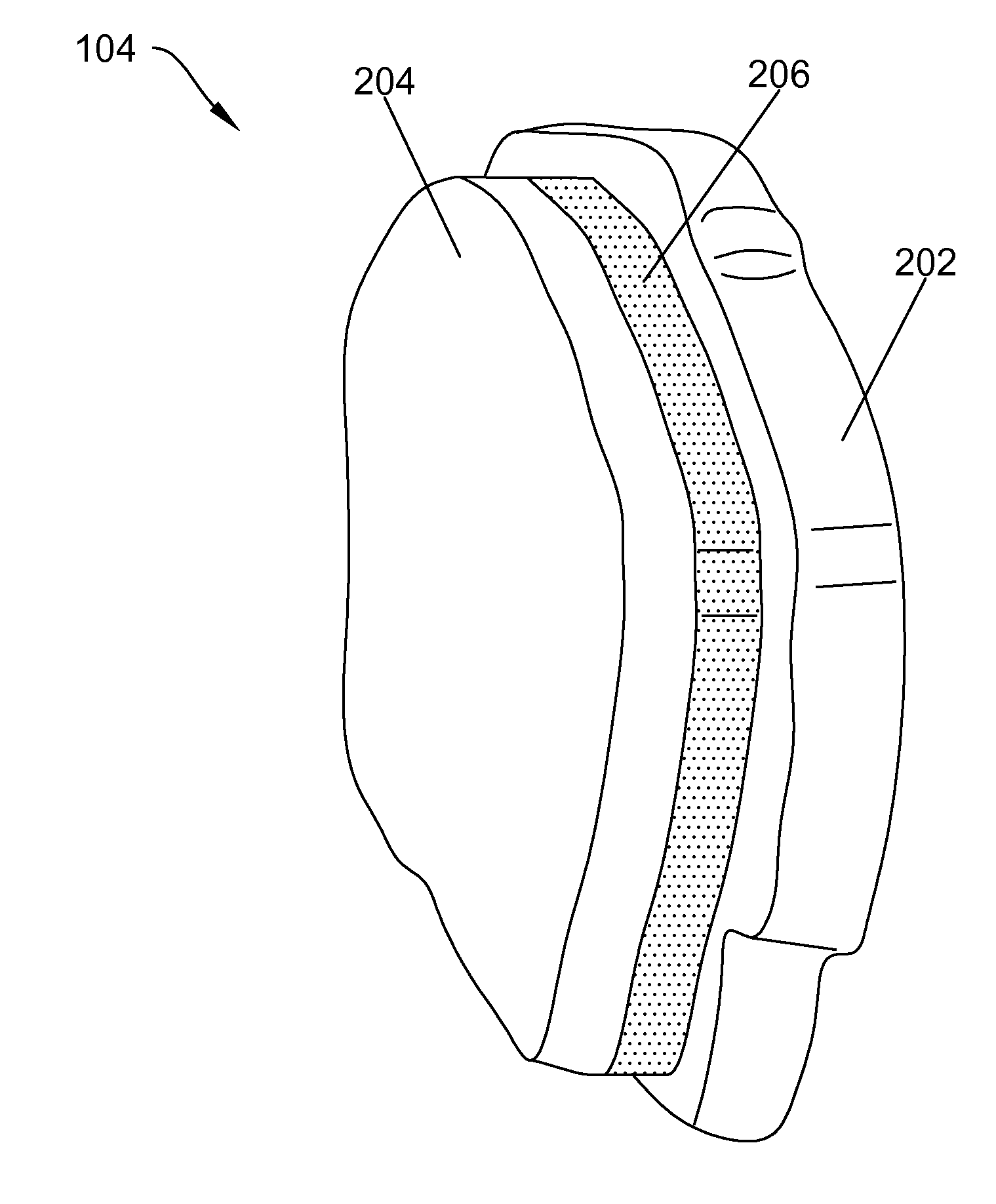
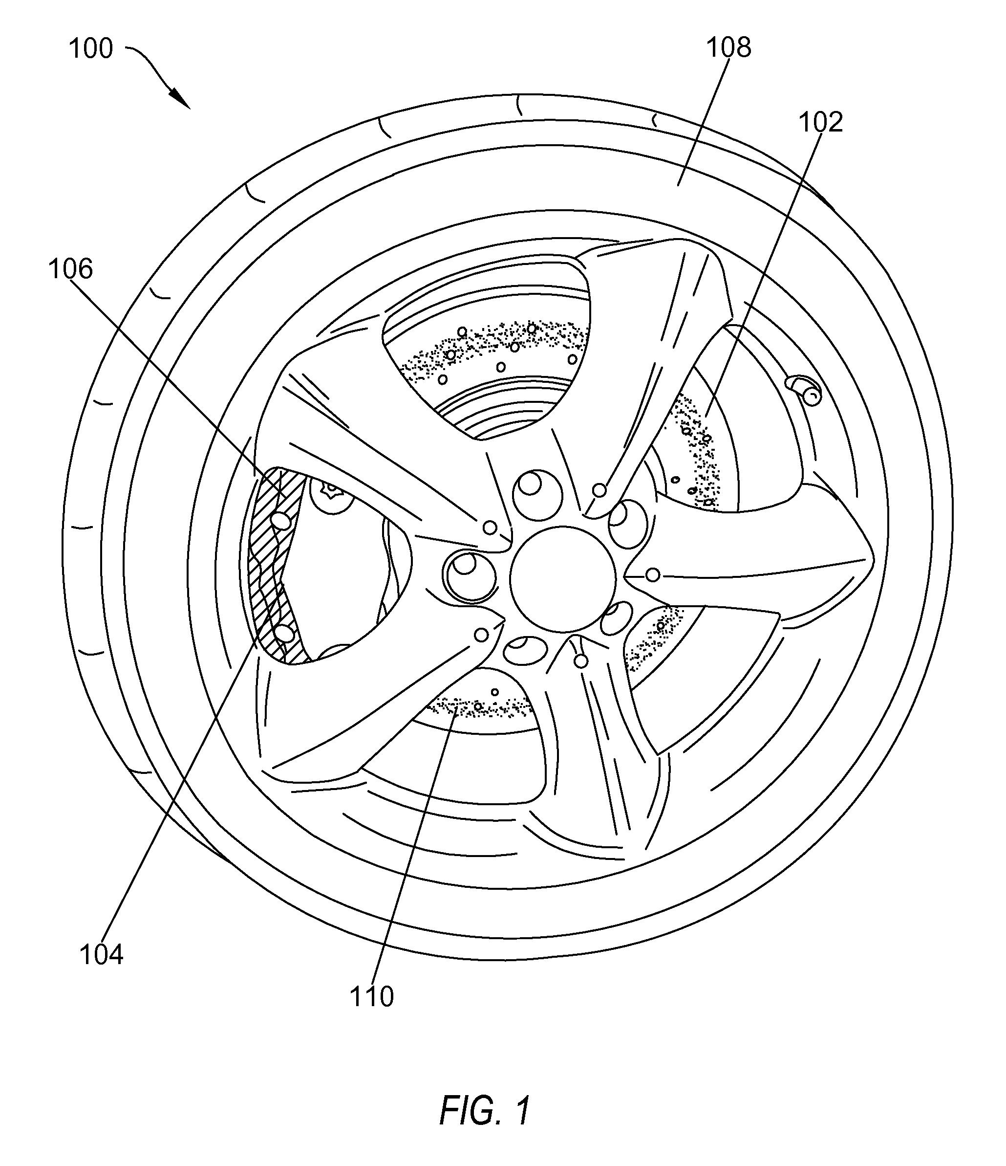
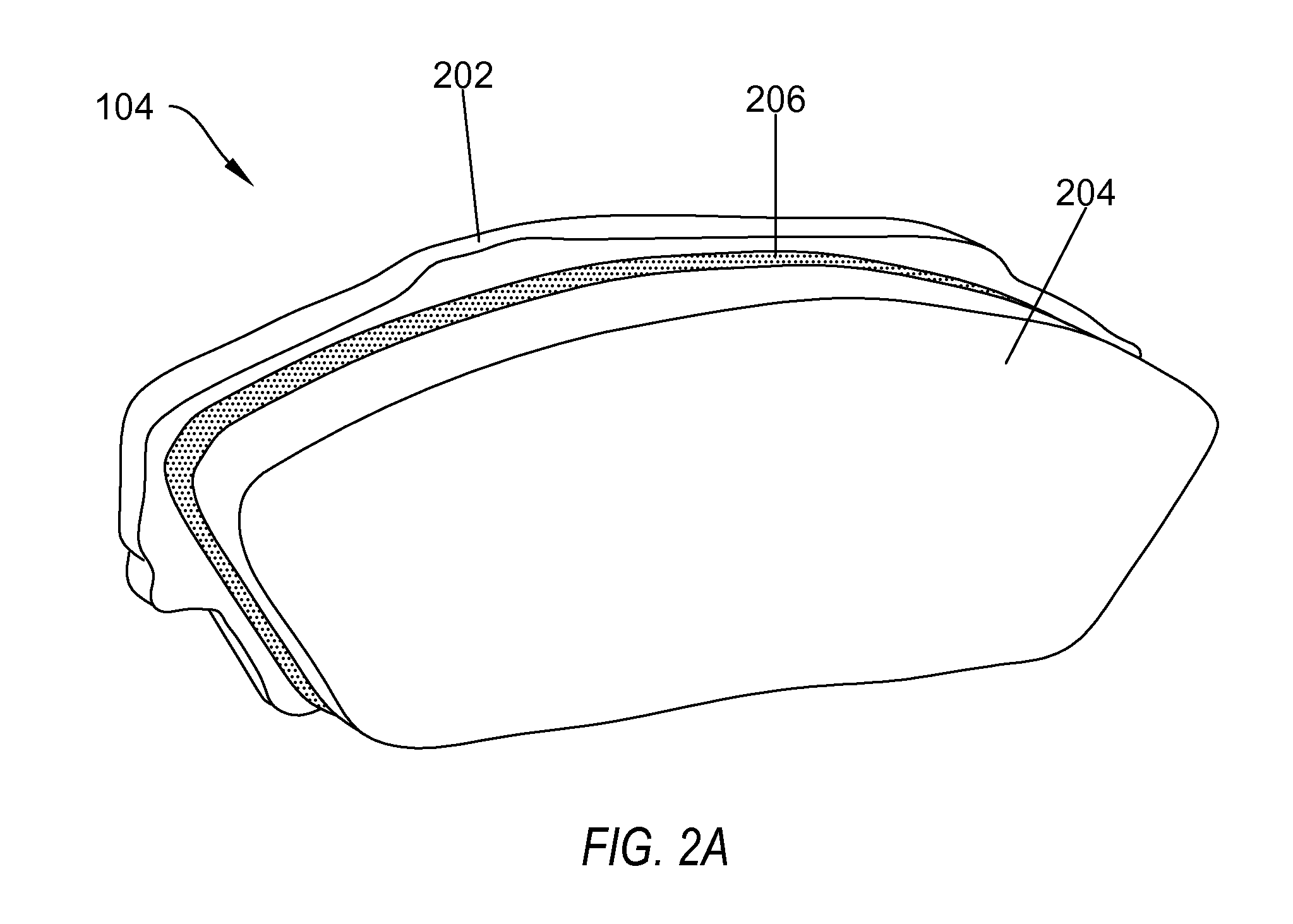
[0007]One example embodiment includes a brake pad which provides a visual indication when the brake pad requires changing. The brake pad includes a first layer, where the first layer includes a material configured to create friction with an external brake disk connected to a wheel. The brake pad also includes a second layer. The second layer includes the material of the first layer. The second layer also includes a dye, wherein the dye is configured to create a visually identifiable dust on the external brake disk.

[0008]Another example embodiment includes a system for braking a wheeled vehicle. The system includes a wear surface,...


PUM

PropertyMeasurementUnit
frictionaaaaaaaaaa
energyaaaaaaaaaa
noiseaaaaaaaaaa

Abstract

One example embodiment includes a brake pad which provides a visual indication when the brake pad requires changing. The brake pad includes a first layer, where the first layer includes a material configured to create friction with an external brake disk connected to a wheel. The brake pad also includes a second layer. The second layer includes the material of the first layer. The second layer also includes a dye, wherein the dye is configured to create a visually identifiable dust on the external brake disk.

Description

CROSS-REFERENCE TO RELATED APPLICATIONS[0001]This application claims the benefit of and priority to U.S. Provisional Patent Application Ser. No. 61 / 485,616 filed on May 12, 2011, which application is incorporated herein by reference in its entirety.BACKGROUND OF THE INVENTION[0002]Brake pads are an important component in helping vehicles to stop their motion. The brake pad is used to transform the rotational motion of the wheels into heat, thus dissipating the energy used to propel the vehicle. However, this can cause a great deal of wear on the brake pad. When the brake pad becomes significantly worn, it can make it difficult or dangerous to stop the vehicle.[0003]There are electronic sensors that can sense this wear and indicate when the brake pads require changing. However, the sensors have thus far proven unreliable. Additionally, these sensors are only available on newer cars. Many brake pads include a material which makes a squealing noise when the pad wears to a certain level...

Claims


Application Information

Patent Timeline
Patent Type & Authority Applications(United States)
IPC IPC(8): F16D66/02B23P11/00
CPCB60T17/22F16D65/092F16D66/022Y10T29/49826F16D2069/005F16D65/005F16D69/00
Inventor MCGEE, ROBERT
Owner MCGEE ROBERT
Learn More