Electric disk brake

Active Publication Date: 2010-03-04
HITACHI ASTEMO LTD
View PDF4 Cites 46 Cited by
  • Summary
  • Abstract
  • Description
  • Claims
  • Application Information

AI Technical Summary

Benefits of technology

[0053]According to the electric disk brake of the present invention, it is possible to

Problems solved by technology

However, a problem may be derived from this re-actuation of the parking brake mechanism; if a vehicle is in such a state that the mechanical lock does not work properly due to a malfunction, once the mechanical lock is released for the purpose of automatic re-actuation of the parking brake mechanism while the vehicle is parked, the relock there

Method used


Image

  • Electric disk brake
  • Electric disk brake
  • Electric disk brake

Examples


first embodiment

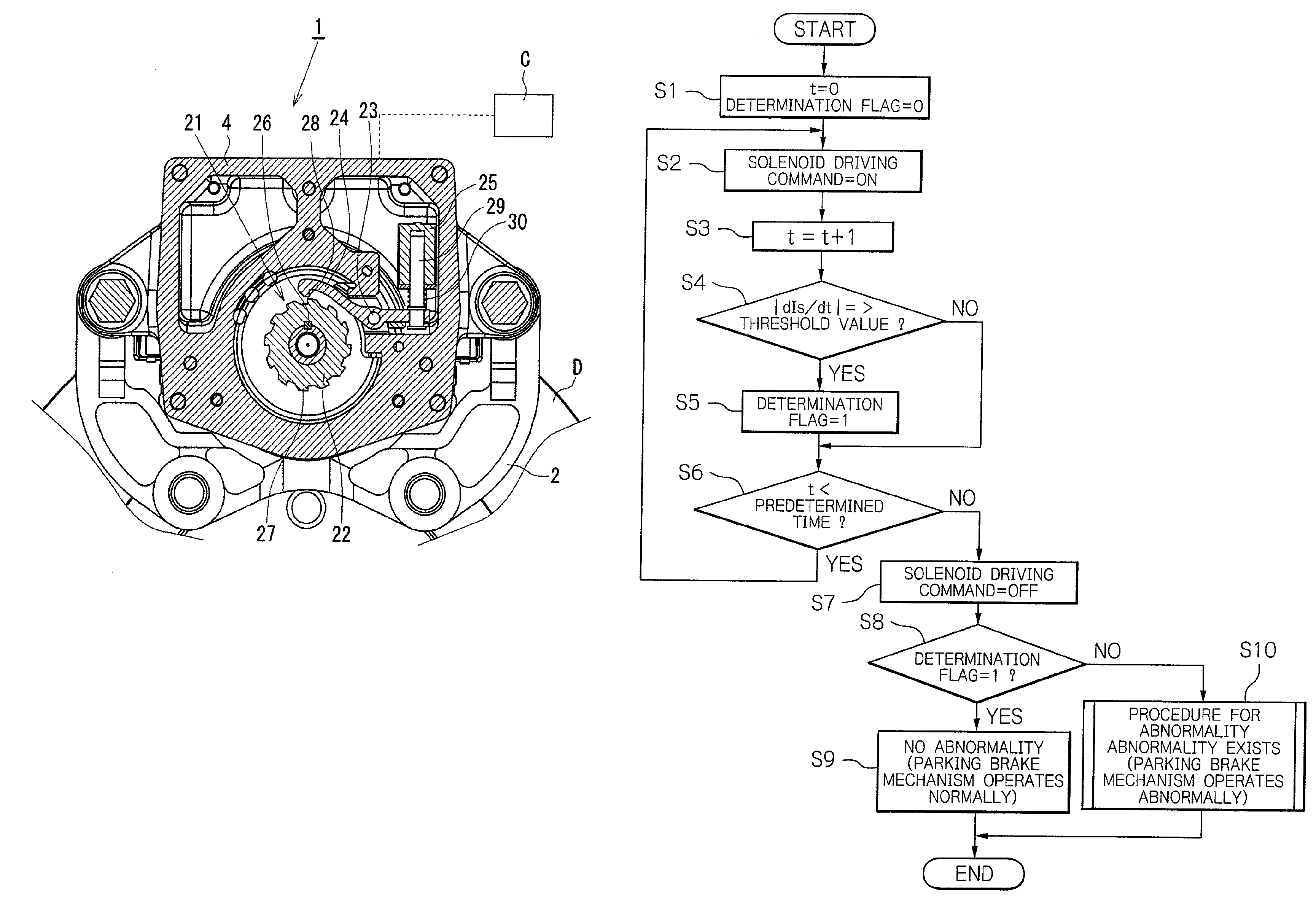
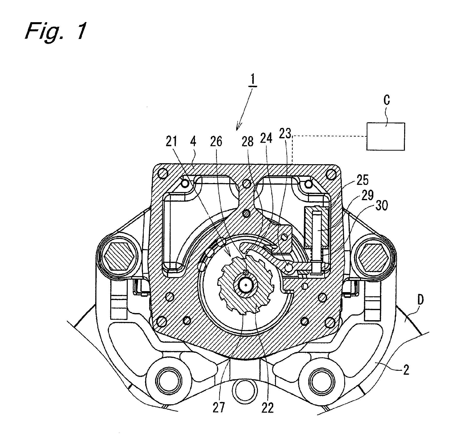
[0073]The engagement pawl 24 extends on the both sides of the pin 23 around which the engagement pawl 24 rotates. An engagement portion 28 is formed at one end of the engagement pawl 24, and engagement and disengagement of the engagement portion 28 with and from one of the teeth 27 of the ratchet wheel 22 is caused by a rotation of the engagement pawl 24 around the pin 23. The teeth 27 of the ratchet wheel 22 and the engagement portion 28 of the engagement pawl 24 each are formed to have a hook-like shape with a surface inclined in a certain direction, and serve as a lock mechanism preventing a rotation of the ratchet wheel 22 in the counterclockwise direction in FIG. 1 (brake releasing direction) when they are engaged with each other. A rotation of the ratchet wheel 22 in the clockwise direction (brake applying direction) generates a force for rotating the engagement pawl 24 in a direction causing the engagement pawl 24 to be disengaged from the tooth 27. In the first embodiment, t...

second embodiment

[0095]As shown in FIG. 6, in the parking brake mechanism of the second embodiment, in a normal state, the engagement pawl 24 abuts against a stopper 32 by receiving a spring force of a coil spring 33, and the engagement portion 28 is disengaged from the tooth 27 of the ratchet wheel 22. A plunger 35 of a solenoid actuator 34 (hereinafter referred to as “solenoid 34”) is situated at a retracted position by receiving a spring force of a return spring 36. Application of an electric current to the solenoid 34 causes the plunger 35 to protrude and the engagement pawl 24 to rotate against the spring force of the coil spring 33, whereby the engagement portion 28 is engaged with the tooth 27 of the ratchet wheel 22. As shown in FIG. 6(c), a predetermined play P is provided between the engagement pawl 24 and the plunger 35 while the engagement portion 28 is engaged with the tooth 27 and the plunger 35 is situated at a retracted position by receiving the spring force of the return spring 36.

[...

third embodiment

[0099]As shown in FIG. 7, an electric disk brake 37 of the third embodiment comprises a ball screw mechanism 38 as a rotation-liner motion converting mechanism. A rotation of a shaft 40 of a motor 39 is slowed down and transmitted to a rotation member 42 by engagement between a pinion 41 attached to the shaft 40 and a spur wheel 43 attached to the rotation member 42 of the ball screw mechanism 38. A rotational motion of the rotation member 42 is converted by the ball screw mechanism 38 into a linear motion of a linear motion member 44 serving as a piston so that the brake pads 3A and 3B are pressed against the disk rotor D, whereby a brake force is generated.

[0100]A parking brake mechanism 45 is disposed at the electric disk brake 37. The parking brake mechanism 45 is configured as follows. A plurality of engagement holes 46 are circumferentially formed at the spur wheel 43, and the spur wheel 43 is prevented from rotating by inserting an engagement pin 47 into one of the engagement...


PUM


Abstract

An object of the present invention is to provide an electric disk brake capable of determining an abnormality of a parking brake mechanism while the parking brake mechanism is in operation. A brake force is generated in the following manner. A rotation of an electric motor is slowed down by a differential speed reducing mechanism, and is converted into a linear motion by a ball ramp mechanism so as to advance a piston, which then presses a brake pad against a disk rotor to generate a brake force. A parking brake mechanism can lock a rotation of a rotor of the electric motor and maintain a braked state by rotating an engagement pawl through a plunger of a solenoid and causing the engagement pawl to be engaged with a ratchet wheel coupled to the rotor of the electric motor. A play is provided at a coupling portion of the engagement pawl and the plunger. The play enables the plunger to move within the range of the play while the engagement pawl is engaged with the ratchet wheel, thereby enabling determination whether the parking brake mechanism operates normally or abnormally based on whether the plunger moves or not upon application of an electric current to the solenoid while the parking brake mechanism is in an actuated state.

Description

BACKGROUND OF THE INVENTION[0001]The present invention relates to an electric disk brake operable to generate a brake force by pressing a brake pad against a disk rotor with use of an electric motor, and in particular, to an electric disk brake comprising a parking brake mechanism capable of holding a brake force while an electric current is not applied.[0002]There is known an electric disk brake which generates a brake force by converting a rotation of a rotor of an electric motor into a linear motion of a piston through a rotation-linear motion converting mechanism such as a ball screw mechanism or a ball ramp mechanism, and pressing a brake pad against a disk rotor by the piston. Such an electric disk brake can generate a desired brake force by detecting a force that a driver applies to a brake pedal (or a displacement amount of the brake pedal) with use of a sensor, and controlling a rotation of the electric motor based on the detection value with use of a control apparatus.[000...

Claims


Application Information

Patent Timeline
IPC IPC(8): B60L7/00F16D65/28F16D65/18
CPCB60T1/005B60T8/885B60T13/741B60T2270/406F16D65/18F16D2129/08F16D2125/36F16D2125/40F16D2125/48F16D2127/06F16D2121/24
Inventor SANO, KAZUMOTOUSUI, TAKUYA
Owner HITACHI ASTEMO LTD
Why Eureka
Try Eureka