Supercharge Your Innovation With Domain-Expert AI Agents!

Selective ion mobility spectrometer

a mobility spectrometer and selective ion technology, applied in the direction of beam deviation/focusing, separation process, instruments, etc., can solve the problems of inability to differentiate between them on the basis of their mass, inability to achieve mobility resolutions which can be achieved in practice, and inability to determine the ratio of ion mass to charge of ion, etc., to achieve the effect of increasing resolution

Active Publication Date: 2012-11-15
BRUKER DALTONIK GMBH & CO KG
View PDF5 Cites 19 Cited by
  • Summary
  • Abstract
  • Description
  • Claims
  • Application Information

AI Technical Summary

Benefits of technology

[0025]In a first embodiment of the invention, the gas flows in one direction only through two mobility filters, thus forming either two ion mobility low pass or two ion mobility high pass filters. If the space between the filters acts as an ion storage volume, e.g. formed by an enveloping RF multipole field, these filters cause ions within a predetermined range of mobilities to collect between the two filters. The ions collected between two consecutive ion mobility low pass filters can be transferred to a detector or an analyzing device, such as a mass spectrometer, by changing the electric field of at least one of the low pass filter. It is advantageous to stop ions from entering the region of the mobility filters before starting the transfer of the collected ions, for example by generating a further electric DC barrier upstream of the first mobility filter. The collected ions in the selected mobility range may finally be investigated in more detail, e.g. by a highly resolved mobility scan of the second filter, or by transferring these ions to a mass spectrometer for the generation and acquisition of fragment ion mass spectra. The two mobility filters are preferably two low pass filters, each formed by electric field barriers, wherein the maximum field strength of the first field barrier is continued as a plateau of essentially constant field strength up to the second field barrier. An ion mobility spectrum can be acquired by a repeated collection of ions of different mobility. The resolution of the mobility spectrum can be adjusted by the difference in field strength between the first and second field barrier. By lowering the difference in field strength, only ions of a narrow mobility range are collected between the filters and, thus, the resolution is increased.

Problems solved by technology

Mass spectrometers can only ever determine the ratio of the ion mass to the charge of the ion.
It is therefore impossible to differentiate between them on the basis of their mass.
Compared to the numerical values for mass resolutions in mass spectrometry, the mobility resolutions which can be achieved in practice are generally very low.
For such combinations, the common high-resolution ion mobility spectrometers of the drift type have the disadvantage of being several meters long.
Because only a moderate amount of ions is trapped in each analyzing cycle, only a limited number of ions of each mobility is available in each single scan, in most cases not enough for a thorough investigation of ions of a selected mobility in a mass spectrometer, for instance, by the generation of fragment ion spectra.

Method used


Image

  • Selective ion mobility spectrometer
  • Selective ion mobility spectrometer
  • Selective ion mobility spectrometer

Examples


second embodiment

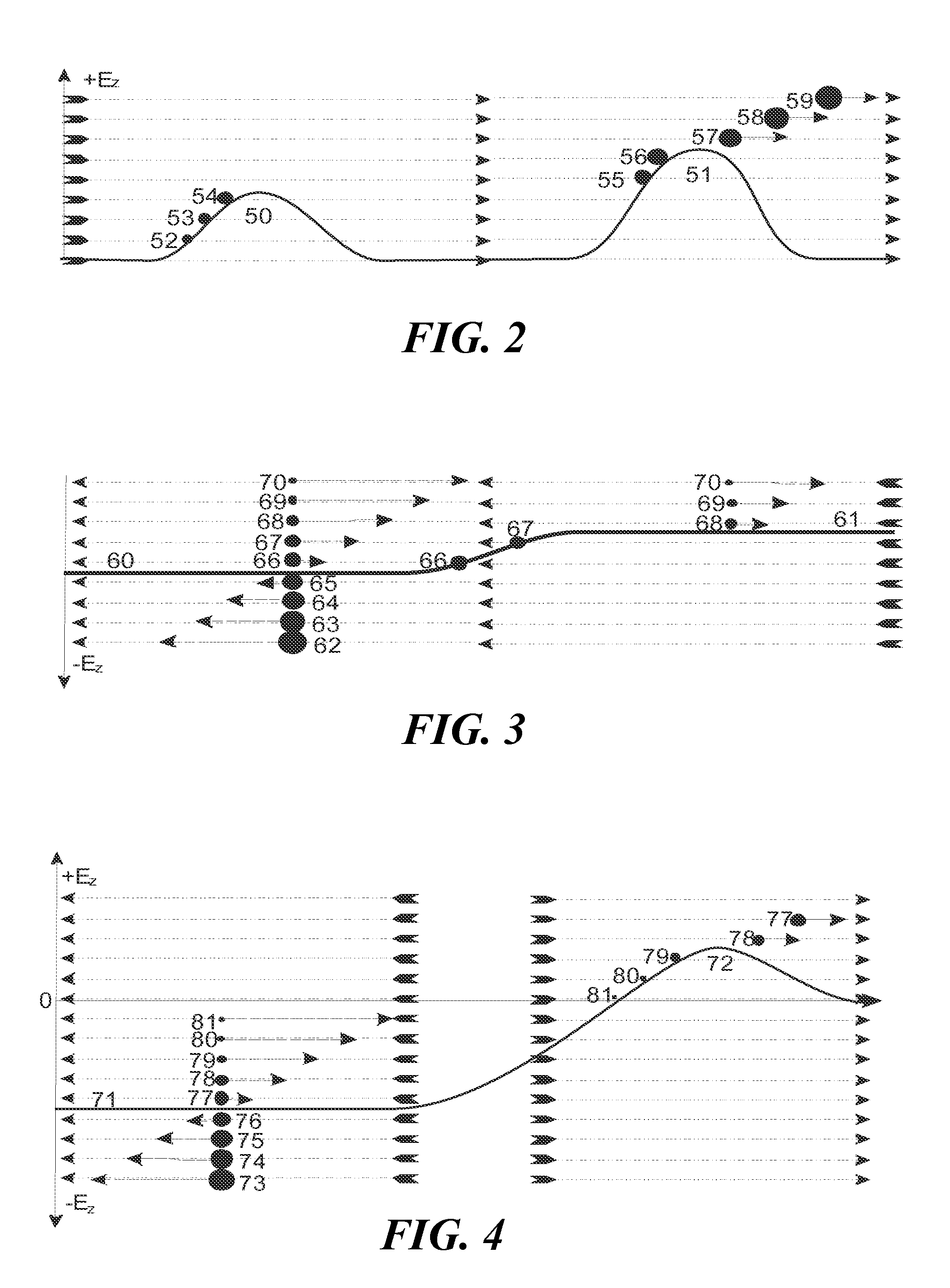
[0043]In a second embodiment, the gas flows in two consecutive filters in different directions, thus producing one high pass and one low pass filter. An example is symbolically presented in FIG. 4. If field strengths and gas flows are adjusted correctly, ions (77) and (78) of a selected range of mobilities can pass both filters, thus forming a continuous current of ions with selected mobilities. In the embodiment shown, gas must be introduced between the two mobility filters, generating two gas flows in two opposing directions. In the first mobility filter, an electric field of controllable strength (71) is adjusted so that it cannot drive ions (73) to (76) with μ3 against the gas flow, thus forming a mobility high pass filter for ions (77) to (81), keeping back the ions of low ion mobility. In the second mobility filter, an electric field barrier (72) in the gas flow forms a mobility low pass filter, and only ions (77) and (78) with mobilities in the range between μ3 and μ4 can suc...

first embodiment

[0046]One arrangement of the method is schematically illustrated in FIGS. 5A-5C, showing the tube (11) with unidirectional gas flow (14) in FIG. 5A, the voltage profile (30) in FIG. 5B, and the two electric barriers (31) and (32) in FIG. 5C. A pattern of electrodes at the inner wall of the tube generates both the RF quadrupole field and the DC potential profile for the DC electric field barriers. The electric field barriers form two ion mobility low pass filters for ions with mobilities μ1 and μ2, respectively. The ions (33) of highest mobility are held back by the first barrier (31), the ions (35) of lowest mobility pass the second barrier (32), and the selected ions (34) of the mobility range between μ1 and μ2 are collected and stored in the quadrupolar RF field of the tube between the two electric barriers (31) and (32) shown in FIG. 5C. These (34) ions may then be investigated in more detail, e.g. by a mobility measurement with highest resolution using the second electric field ...


PUM


Abstract

Ions with a predetermined ion mobility range are produced by filtering ions entrained in a stream of moving gas with two ion mobility low pass filters located consecutively in the gas stream. Each filter is formed by applying a DC electric field to the gas stream which causes the ions to move in a direction opposite to the gas flow. Ions are collected between the two filters and transferred to a detector or analyzing device. In one embodiment, the maximum field strength of the electric field barrier in the first ion mobility low pass filter is continued as a plateau of essentially constant field strength up to the electric field barrier in the second ion mobility low pass filter, which has a maximum field strength higher that the maximum field strength of the electric field barrier in the first ion mobility low pass filter.

Description

BACKGROUND[0001]The invention relates to the selection of ions of a predetermined range of mobilities, preferably for being analyzed by mass spectrometry. Mass spectrometers can only ever determine the ratio of the ion mass to the charge of the ion. Where the terms “mass of an ion” or “ion mass” are used below for simplification, they always refer to the ratio of the mass m to the dimensionless number of elementary charges z of the ion. This charge-related mass m / z has the physical dimension of a mass, but it is often also called “mass-to-charge ratio”, although this is incorrect with regard to the physical dimension. The term “ion species” shall denote ions having the same chemical formula, the same charge and the same three-dimensional structure. Ion species generally comprise all ions of an isotope pattern containing ions of slightly different masses, but virtually the same mobilities.[0002]Different kinds of isomers are known for bioorganic molecules: isomers related to the prim...

Claims


Application Information

Patent Timeline
IPC IPC(8): H01J3/26H01J49/26
CPCG01N27/622G01N27/623
Inventor PARK, MELVIN ANDREWKAPLAN, DESMOND ALLENRIDGEWAY, MARK
Owner BRUKER DALTONIK GMBH & CO KG
Features
  • R&D
  • Intellectual Property
  • Life Sciences
  • Materials
  • Tech Scout
  • Unparalleled Data Quality
  • Higher Quality Content
  • 60% Fewer Hallucinations
Learn More