Apparatus and method for energy storage with relativistic particle acceleration

a technology of relativistic particle and apparatus, applied in the direction of electromagnetic induction accelerators, accelerators, electrical apparatus, etc., can solve the problems of low energy density of systems that can be produced synthetically and economically, environmental damage, and low energy density of systems, etc., to achieve limited or no energy loss, maximize beam energy, and reduce the effect of energy loss

Inactive Publication Date: 2012-11-15
BAZAZ GAURAV
View PDF15 Cites 7 Cited by
  • Summary
  • Abstract
  • Description
  • Claims
  • Application Information

AI Technical Summary

Benefits of technology

[0006]The model of the present invention relies on accelerating particles to very high velocities within a confined enclosure and holding them at the high velocity in a vacuum chamber. In one embodiment, the particles are charged particles such as protons or electrons, which are accelerated using an accelerator within a circular ring vacuum cavity to very high velocities, approaching the speed of light, though considerably less than the velocities seen in particle colliders such as LHC in Geneva. As particles are accelerated, their kinetic energy (KE) increases, and is stored in their continuous motion in a closed loop. The particles are held within the confined enclosure of the vacuum rings by the application of appropriate magnetic fields and/or electric fields. Charged particles moving in the xy-plane can be held in a fixed circular path without loss of energy when a magnetic field is applied along the z-axis. Similarly, a charged particle beam can be bent in its path by the application of an electric field perpendicular to the beam path, with very limited or no loss of energy. A good analogy to the present invention is the model of particle colliders such as the Tevatron at Fermilab. However, present invention doesn't accelerate individual particles to velocities anywhere near the velocities such facilities accelerate particles to and therefore is much smaller and less expensive. When energy

Problems solved by technology

All current models suffer from one of two, or both, problems—High energy density options, such as fossil fuels, are environmentally destructive and can't feasibly be manufactured synthetically in an economical way.
On the other hand, systems that can be produced syn

Method used


Image

  • Apparatus and method for energy storage with relativistic particle acceleration
  • Apparatus and method for energy storage with relativistic particle acceleration
  • Apparatus and method for energy storage with relativistic particle acceleration

Examples


Embodiment Construction

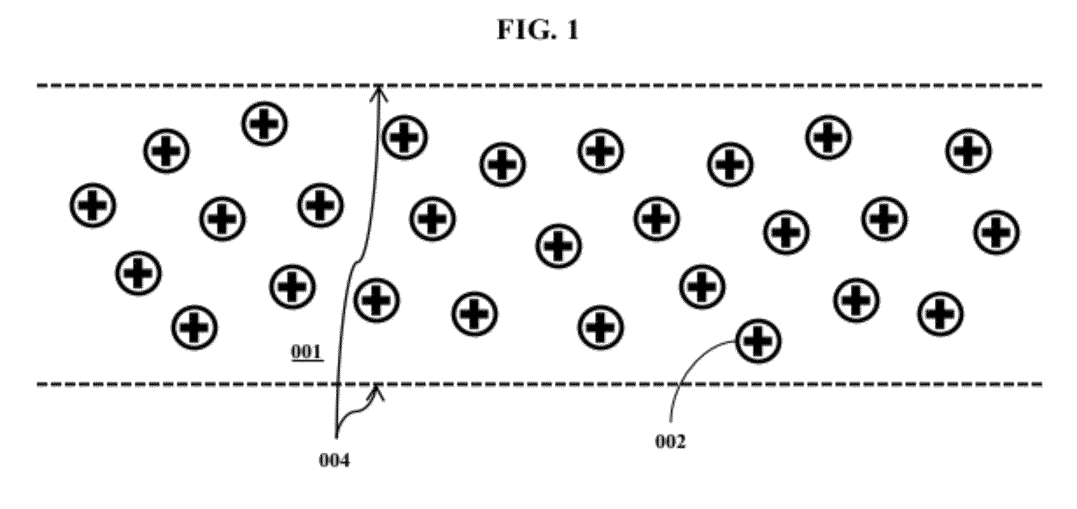
[0054]FIG. 1 shows a very simplified view of a charged particle beam. The beam volume 001 is confined within the beam edges 004. The beam consists of many positively charged particles 002 as this is a proton beam. The beam actually used in a given embodiment of the device can vary based on various design considerations. Also, the beam edges 004 only delineate the surface within which most of the mass of the beam is located and are purely conceptual entities. Similarly, the beam particles need not necessarily be protons, and can be of various other particle species, positively or negatively charged with any physically possible net charge. The charged particles 002 in the beam are all of the same charge and therefore repel each other. The more we try to focus the beam, the lesser the space between particles and greater their mutual repulsion. Therefore, a beam consisting of such particles will tend to spread out and disintegrate over time unless an external influence forces the partic...


PUM


Abstract

An energy storage device is proposed that utilizes acceleration of particles to near relativistic velocities to store energy in the kinetic energy of accelerated particles. Designs and models are provided for a commercially feasible device that implements the concept. The device allows tremendous performance capabilities across many parameters including energy density. Multiple innovations are also proposed for methods to reconvert the kinetic energy of accelerated particles back to electricity. In addition, certain innovations are proposed for accelerated particle beam control, beam particle designs and beam confinement rings. The device is different from existing particle collider storage rings in that it maximizes total beam energy, not energy per particle by accelerating particles to velocities substantially less than the speed of light. In addition, it includes innovations to meet the requirements of the commercial market with specific applications in markets such as grid level storage and energy storage for vehicles.

Description

RELATED APPLICATION[0001]This application claims the benefit of priority to U.S. Provisional Application 61 / 484,009 filed 9 May 2011, the entire disclosure of which is incorporated herein by reference.FIELD OF THE INVENTION[0002]The present invention relates to storage of energy in very large quantities utilizing the kinetic energy of particles accelerated to near relativistic velocities but substantially less than the speed of light which permits reduction in cost and size of the device while storing large amounts of energy. In addition the invention concerns the design of particle beams with much larger beam mass than is usually observed in particle beams in applications such as particle colliders. Lastly, the invention proposes various methods for reconversion of kinetic energy of accelerated particles to electricity with high levels of efficiency and at economical costs.BACKGROUND[0003]Current models for energy storage primarily rely on storage in static energy fields. Most comm...

Claims


Application Information

Patent Timeline
IPC IPC(8): H05H7/04H05H7/18
CPCH05H11/00H05H7/04
Inventor BAZAZ, GAURAV
Owner BAZAZ GAURAV
Why Eureka
Try Eureka