
Liquid crystal display

a liquid crystal display and display technology, applied in the field of display, can solve problems such as affecting and achieve the effect of improving the display quality of the lcd and reducing cross nois

Active Publication Date: 2012-11-15
SHENZHEN CHINA STAR OPTOELECTRONICS TECH CO LTD
View PDF1 Cites 7 Cited by
  • Summary
  • Abstract
  • Description
  • Claims
  • Application Information

AI Technical Summary

Benefits of technology

[0010]The main object of this invention is to provide an LCD, which has the advantages of reducing the cross noise and improving the display quality of the LCD.
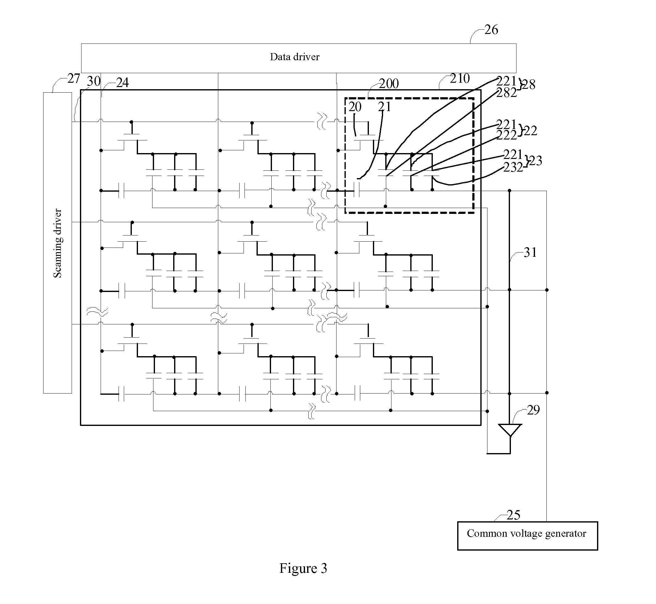
[0029]Compared with the prior art, the LCD provided by this invention further includes a pixel voltage adjuster. The pixel voltage adjuster can receive the feedback common voltage from the common electrode and adjust the voltage of the pixel electrode according to the feedback common voltage, so that the voltage of pixel electrode keeps the synchronous change with the common voltage, thereby compensating the fluctuation of the common voltage, effectively improving the phenomenon of cross noise, and raising the display quality of the LCD.

Problems solved by technology

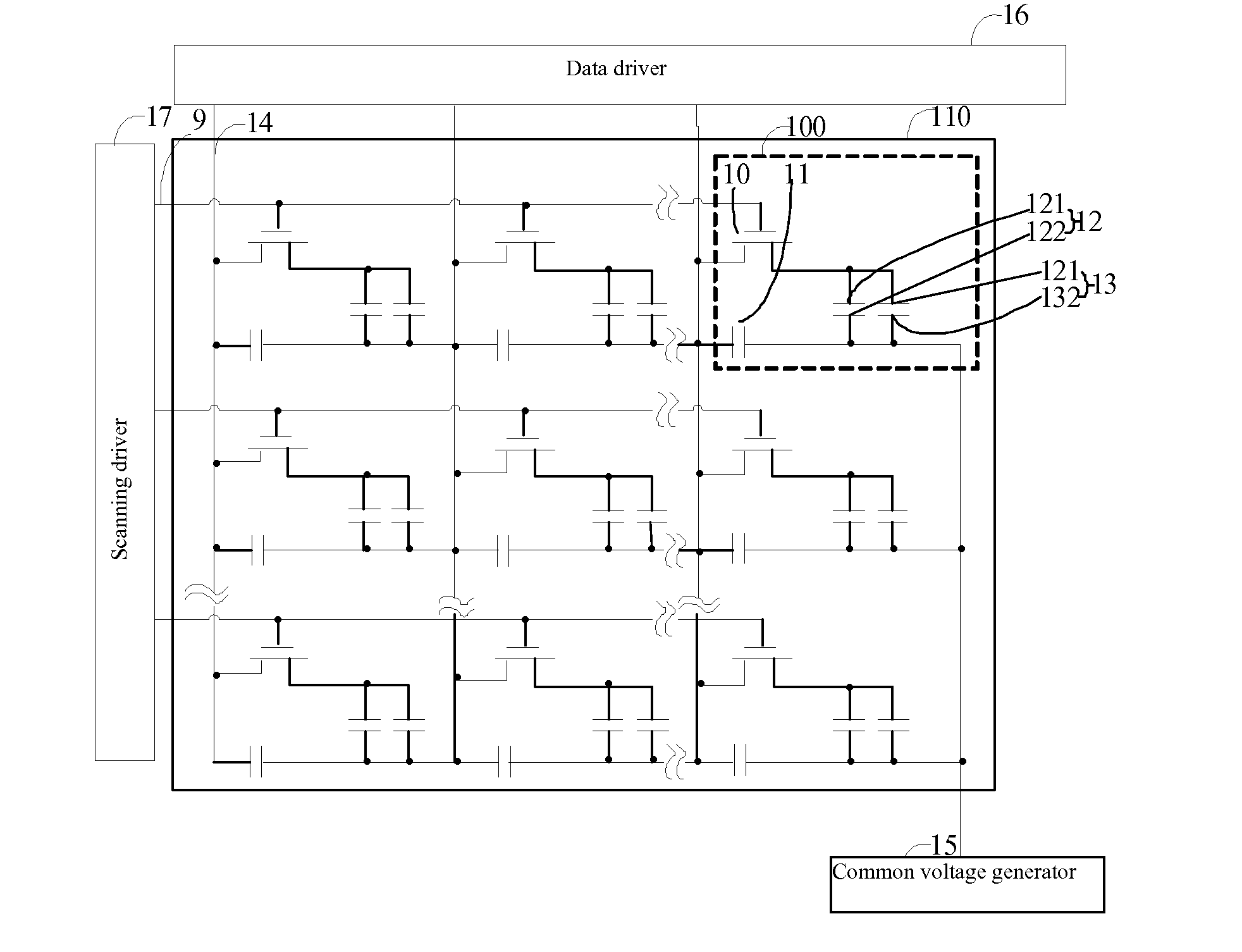
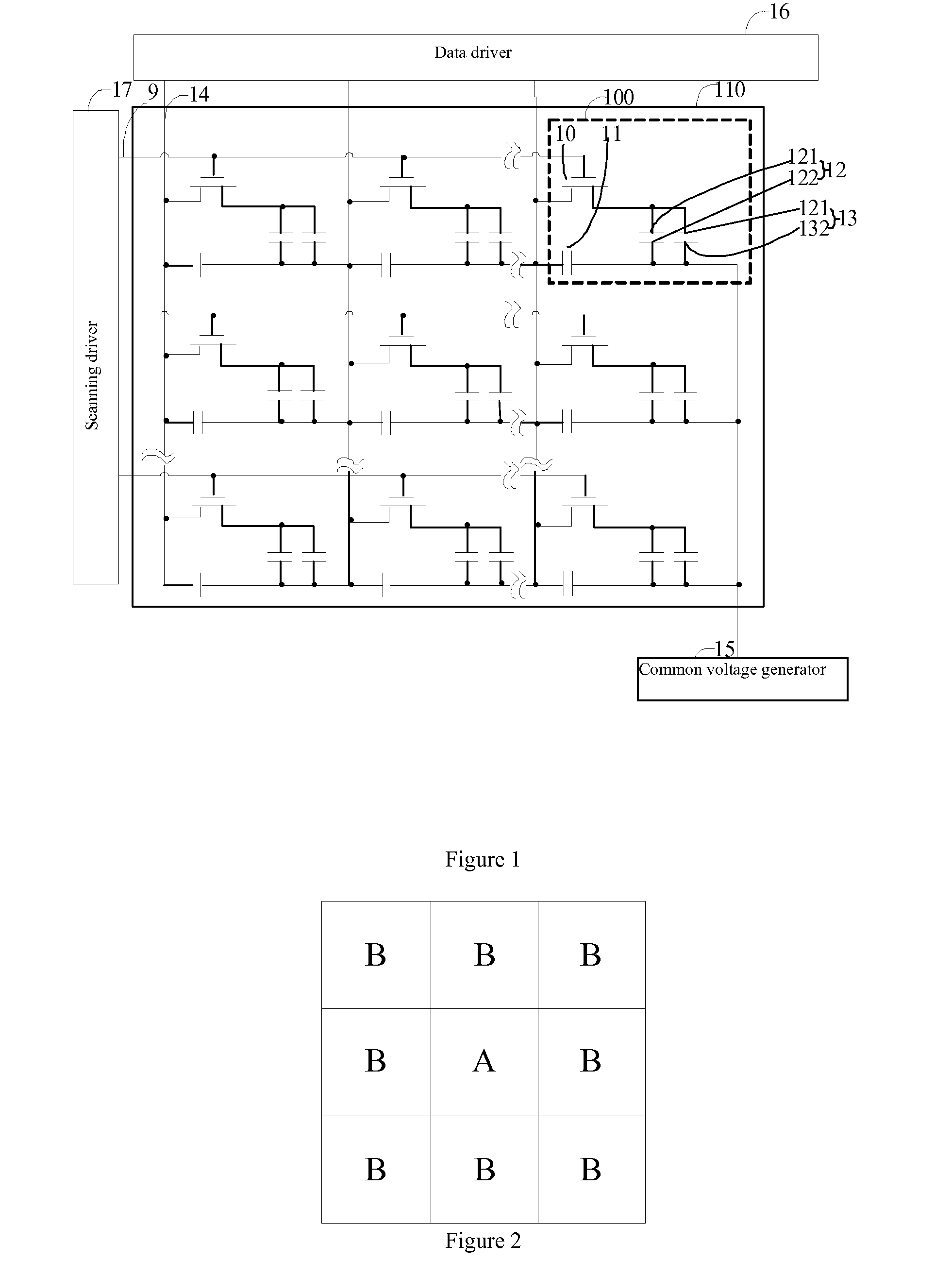
Likewise, the problem that the voltage of the common electrode 122 fluctuates upwards or downwards exists in a plurality of single pixel units 100 of the LCD, and the common electrodes 122 of the pixel units 100 are communicated, therefore, the problem that the whole voltage of the common electrode 122 of the LCD fluctuates upwards or downwards easily generates the phenomenon of cross noise, thereby greatly influencing the display quality of the LCD.

Method used


Image

  • Liquid crystal display
  • Liquid crystal display
  • Liquid crystal display

Examples


first embodiment

[0036]Please refer to FIG. 3. FIG. 3 is the schematic diagram for the circuit structure of the LCD provided in this invention. The LCD includes an LCD panel 210, a common voltage generator 25, a pixel voltage adjuster, a scanning driver 27 and a data driver 26, wherein the pixel voltage adjuster includes a plurality of compensation capacitors 28 and a unity gain amplifier 29. The LCD can be the LCD in a size smaller than or equal to 32 inches.

[0037]The LCD panel 210 includes a plurality of scanning lines 30 and a plurality of data lines. The scanning lines 30 and the data lines 24 are crosswise arranged by way of insulation to define a plurality of pixel units 200 arranged in the way of a matrix. Each pixel unit 200 is provided with a thin film transistor 20, a liquid crystal capacitor 22, a storage capacitor 23 and the compensation capacitor 28. The liquid crystal capacitor 22 includes a pixel electrode 221 and a common electrode 222 oppositely arranged and a liquid crystal layer (...

second embodiment

[0047]The LCD provided in this invention is not limited to what the first and the second embodiment have stated, and the number of unity gain amplifiers is not limited to one or two, which can be more according to the increase of the size of LCD, and the location of unity gain amplifiers also can be arranged in terms of actual needs.

[0048]The statements are preferable embodiments in this invention, not limiting the scope of patent of this invention thereof. Equivalent structures or equivalent transformation processes made with contents of the description and figures of this invention, or applying the contents of the description and figures of this invention in other relevant technical fields are all included in the scope of patent protection of this invention for the same reason.


PUM


Abstract

This invention discloses an LCD which includes an LCD panel and a pixel voltage adjuster. The LCD panel includes a plurality of pixel units which are arranged in the way of a matrix. Each pixel unit is provided with a liquid crystal capacitor. The liquid crystal capacitor includes a pixel electrode and a common electrode oppositely arranged. The pixel voltage adjuster receives a feedback common voltage from the common electrode and adjusts the voltage of the pixel electrode in terms of the feedback common voltage. The LCD provided in this invention can reduce cross-noise and improve the display quality of the LCD.

Description

FIELD OF THE INVENTION[0001]This invention relates to the technical field of display, particularly to a liquid crystal display.BACKGROUND OF THE INVENTION[0002]A liquid crystal display (LCD) is a flat panel display widely used at present, which has the advantages of thin and light appearance, electricity economization and no radiation. The operating principle of LCD is that the voltage difference at the two ends of a liquid crystal layer is utilized to change the arrangement state of liquid crystal molecules in the liquid crystal layer, so as to change the light transmission of the liquid crystal layer, and display the image by cooperating the light source provided by a backlight module.[0003]FIG. 1 is the schematic diagram for the circuit structure of an existing LCD. The LCD includes an LCD panel 110, a common voltage generator 15, a scanning driver 17 and a data driver 16, wherein the LCD panel 110 includes a plurality of scanning lines 9 and a plurality of data lines 14, the sca...

Claims


Application Information

Patent Timeline
Patent Type & Authority Applications(United States)
IPC IPC(8): G09G5/00G09G3/36
CPCG09G3/3655G09G2320/0209G09G2300/0876G09G2300/043G09G2300/0852G09G3/3666
Inventor ZHAO, DENGXIA
Owner SHENZHEN CHINA STAR OPTOELECTRONICS TECH CO LTD
Learn More