Determination of a position characteristic for an object

Active Publication Date: 2012-11-15
KONINKLIJKE PHILIPS ELECTRONICS NV
View PDF5 Cites 18 Cited by
  • Summary
  • Abstract
  • Description
  • Claims
  • Application Information

AI Technical Summary

Benefits of technology

[0017]The optically identifiable element may be placed on a wall proximal to a floor of the room. For example, the largest distance from the floor to a part of the optically identifiable element may no more than 50 cm, 20 cm, 10 cm, 5 cm or even 1 cm. This may provide improved detection of e.g. feet which are particularly relevant for e.g. detecting a presence of a person. It may also reduce the visual impact of the optically identifiable element. In some scenarios, the optically identifiable element may extend upwards from the intersection of the wall with the floor of the room.
[0018]The optically identifiable element may contain a calibration pattern to facilitate position calibration. For instance, a red fluorescent tape can contain a 1 cm wide black part every 1 m along the tape length. If we assume that the wall is straight the camera sensors can detect the black parts since these form occlusions. The camera sensors can use them to establish a relation between camera coordinates and room coordinates.

Problems solved by technology

However, estimations of (in particular) positions of creatures in a room may be particularly difficult as the algorithms must take into account that many parameters and characteristics of the environment will be varying with time and/or will be unknown.
However, the interpretation of the images from such cameras is very complex, and in particular it is very difficult to reliably identify the image segments corresponding to the objects of inte

Method used


Image

  • Determination of a position characteristic for an object
  • Determination of a position characteristic for an object
  • Determination of a position characteristic for an object

Examples


Embodiment Construction

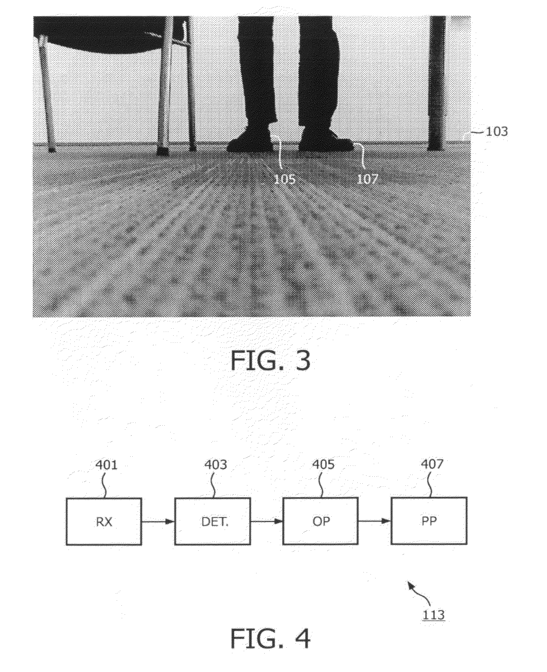
[0074]The following description focuses on embodiments of the invention applicable to a system for detection of the presence of people in a room. However, it will be appreciated that the invention is not limited to this application but may be applied to many other applications and objects.

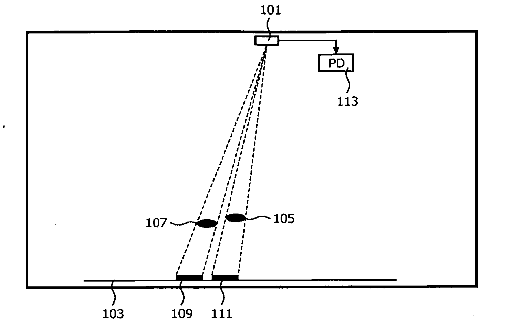
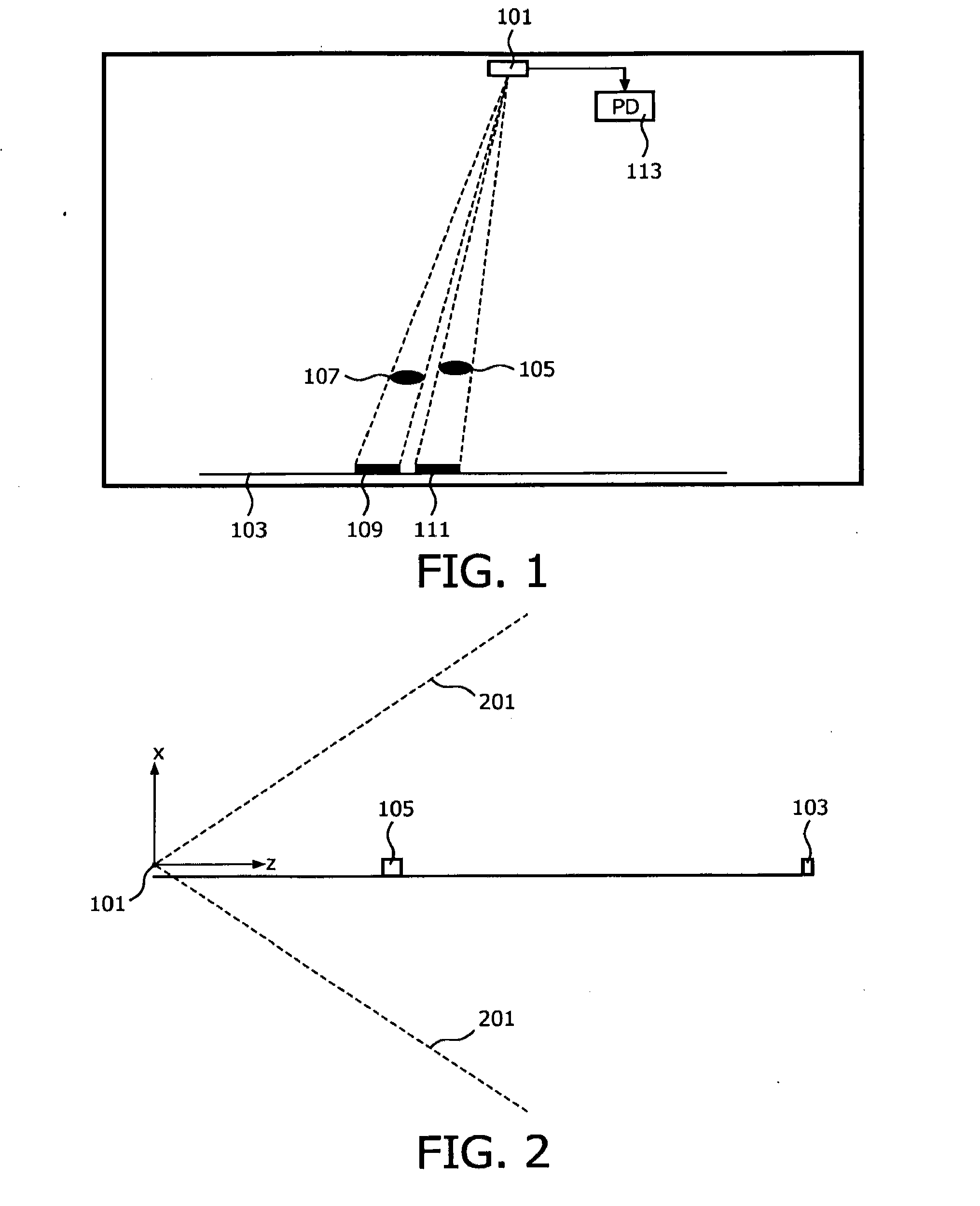
[0075]In the following, a system will be described which is arranged to determine characteristics of an object which may be placed in a room based on images captured by one or more video cameras. Specifically, a depth position may be determined which comprises an estimate of the position of a potential object in the room in a direction which is perpendicular to the image plane of the camera. Thus, the system may allow a determination of a position estimate for a position component along the optical axis of the camera. The system may in addition determine one or more position estimates for the object in a direction that is parallel to the image plane and may specifically determine a three dimensiona...


PUM


Abstract

A system for determining a position characteristic for an object in a room comprises an optically identifiable element (103) positioned on a background surface for a detection area of the room. A camera (101) is positioned across the detection area from the optically identifiable element (103) and captures an image comprising the detection area and the optically identifiable element (103). A detector (403) detects the optically identifiable element (103) in the image based on an optical property. An occlusion processor (405) determines an occlusion property for an occlusion of the optically identifiable element (103) in the image in response to the optical property. A position processor (407) determines a depth position in response to the occlusion property where, the depth position is indicative of a position of the object along the optical axis of the camera (101). The invention may for example allow presence detection and rough localization of a person in a room.

Description

FIELD OF THE INVENTION[0001]The invention relates to a determination of a position characteristic for an object and in particular, but not exclusively, to determination of a depth position for a creature in a room.BACKGROUND OF THE INVENTION[0002]Determination of positions of objects and in particular of living beings, such as humans or pets, is of increasing interest in many applications. Position estimates may for example be used for the prevention and / or detection of accidents. For example, it may be used to detect that an elderly person has fallen down or that a small child climbs on a table with the risk of falling down. However, estimations of (in particular) positions of creatures in a room may be particularly difficult as the algorithms must take into account that many parameters and characteristics of the environment will be varying with time and / or will be unknown. For example, the specific characteristics of the object that is to be detected may be unknown, and the differ...

Claims


Application Information

Patent Timeline
IPC IPC(8): H04N7/18
CPCG06T7/004G06T7/70G06T7/50G06T7/60G06T2207/30196G06T2207/10G06V40/10
Inventor VAREKAMP, CHRISTIAANVANDEWALLE, PATRICK LUC E.MERTENS, MARK JOZEF WILLEM
Owner KONINKLIJKE PHILIPS ELECTRONICS NV
Why Eureka
Try Eureka