
Recessed Lighting Fixture and Flexibly Attached Compact Junction Box

a compact junction box and recessed lighting technology, applied in the field of recessed lighting fixtures and junction boxes, can solve the problems of difficult installation and removal of many l-shaped retrofit assemblies, challenging miniaturization of junction boxes, etc., and achieve the effect of preventing undue strain on the flexible conduit and preventing undue strain on the wiring and its connections

Active Publication Date: 2012-11-15
HUBBELL LIGHTING INC
View PDF0 Cites 32 Cited by
  • Summary
  • Abstract
  • Description
  • Claims
  • Application Information

AI Technical Summary

Benefits of technology

[0010]The invention also concerns a lighting fixture assembly that includes a junction box or junction box assembly as described above flexibly attached to a lamp housing containing a lamp assembly. A flexible conduit interconnects the junction box and the lamp housing with wiring therein for supplying power to the lamp assembly. A flexible tether, which preferably runs through the flexible conduit, has one end anchored to the lamp housing and the other end anchored to the junction box. The length of the tether prevents undue strain on the wiring and its connections, and preferably prevents undue strain on the flexible conduit.

Problems solved by technology

Many L-shaped retrofit assemblies can be somewhat difficult to install and remove, especially in situations where joist spacing is tight or where obstructions such as joist blocking, ductwork or piping are located close to the lighting fixture installation hole.
Further, the small installation holes (e.g., 2⅞ inch or smaller) required for small aperture lamp housings make junction box miniaturization challenging, especially where the junction box must house a transformer, driver or other component.

Method used


Image

  • Recessed Lighting Fixture and Flexibly Attached Compact Junction Box
  • Recessed Lighting Fixture and Flexibly Attached Compact Junction Box
  • Recessed Lighting Fixture and Flexibly Attached Compact Junction Box

Examples


Embodiment Construction

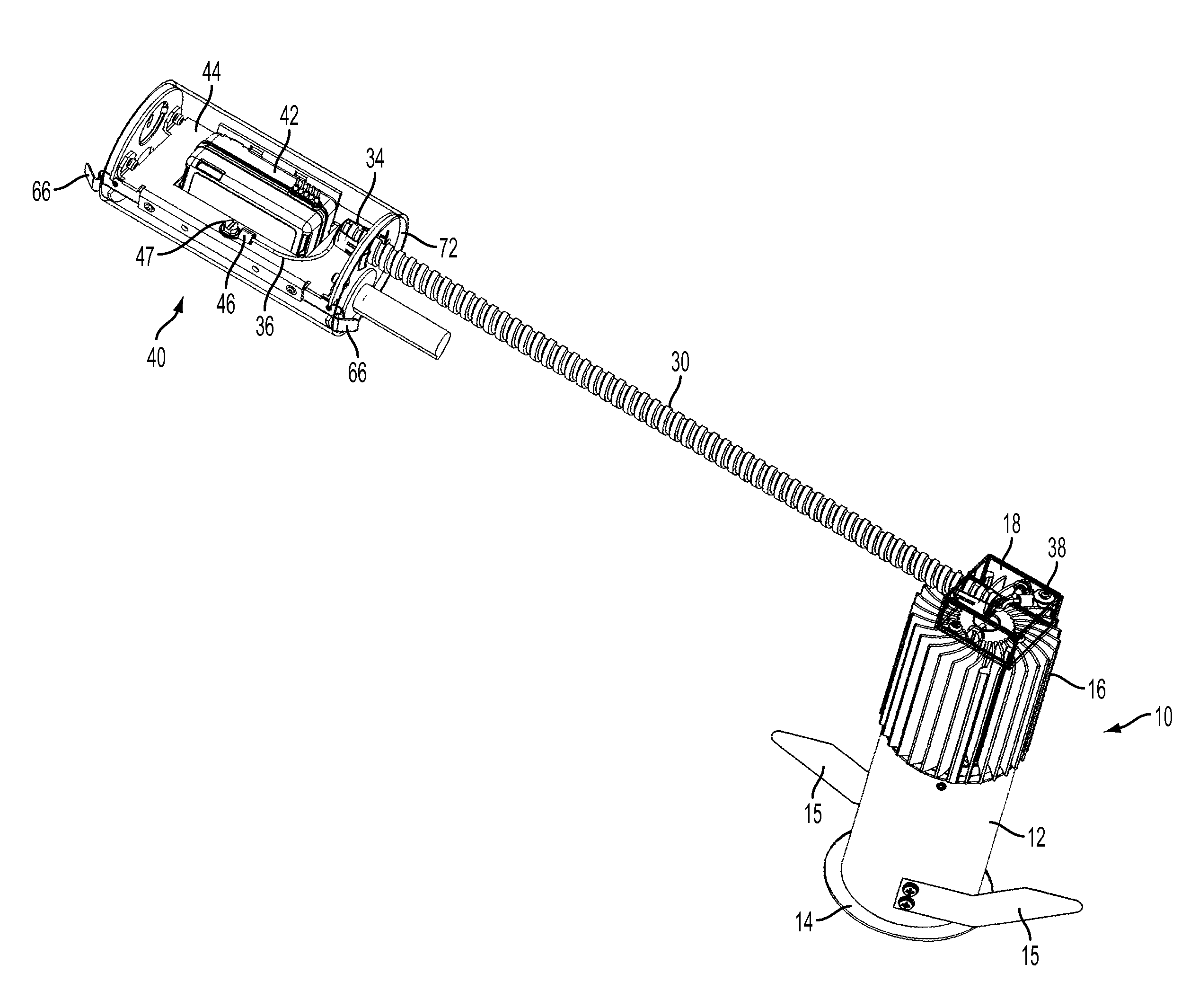
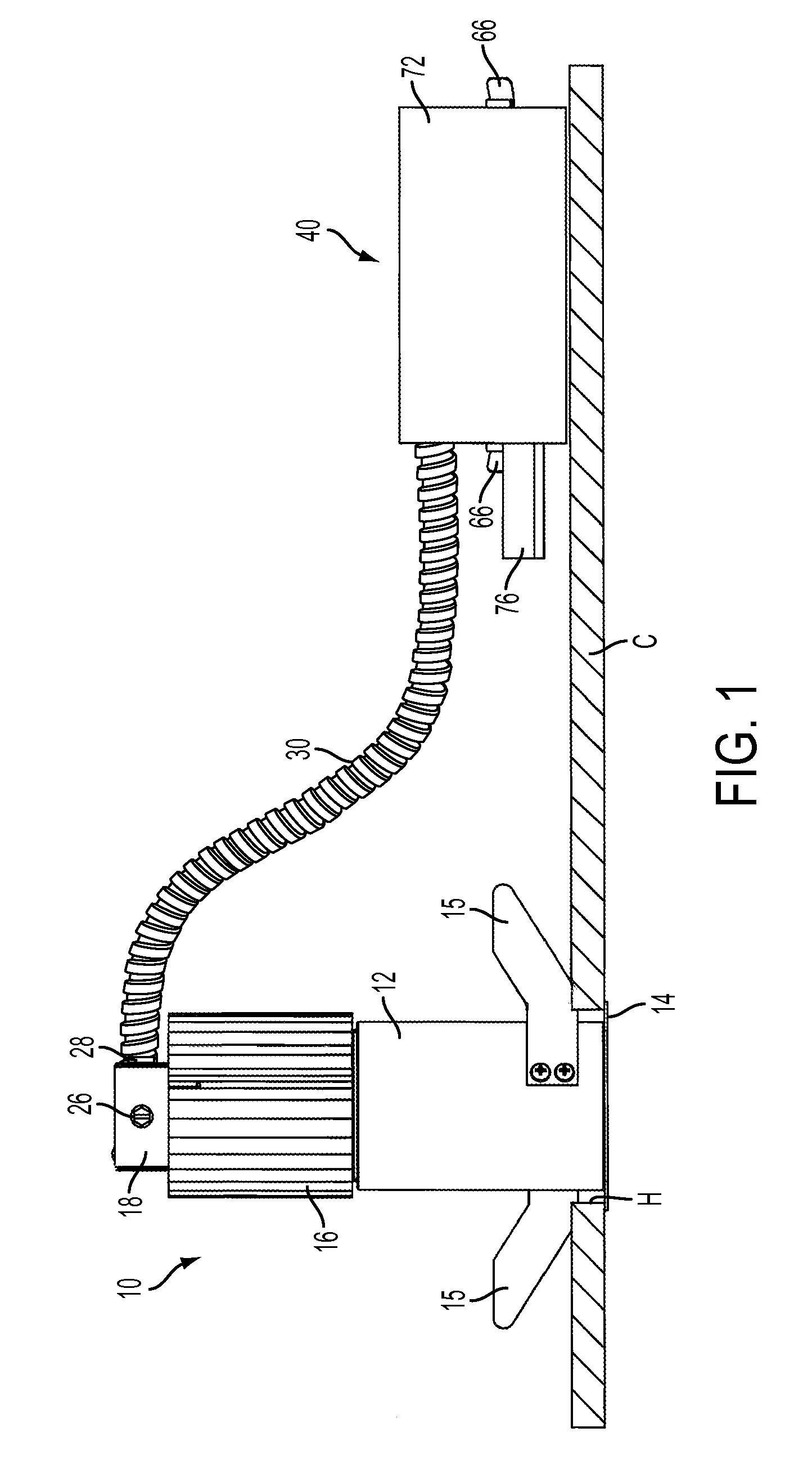
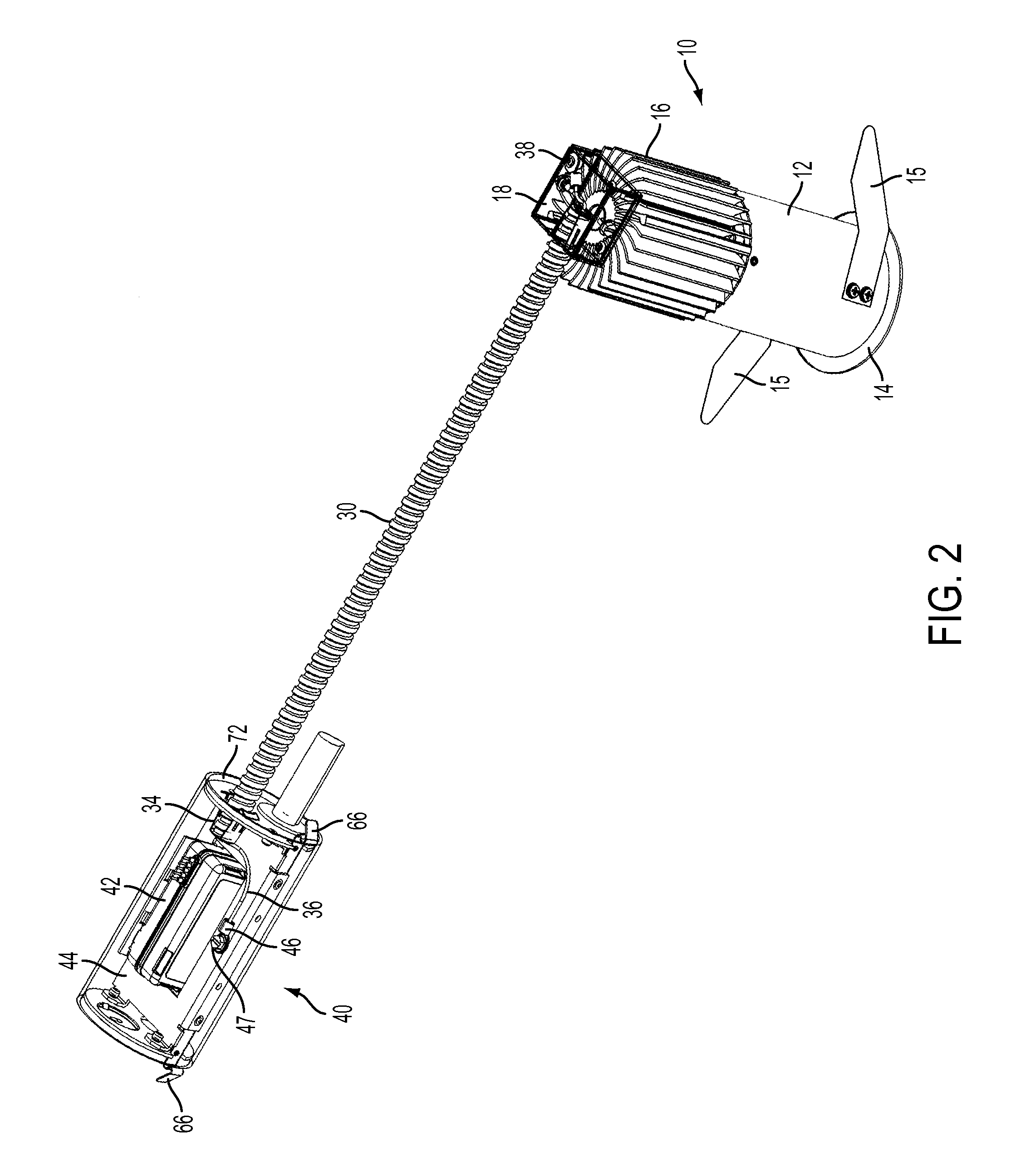
[0028]Referring to FIGS. 1-5, a lighting fixture according to the invention comprises a lamp housing 10, a junction box assembly 40 and a flexible metal conduit 30 interconnecting the lamp housing and the junction box and protecting wiring within. Lamp housing 10 comprises a metallic tubular lower body 12, a finned metallic upper housing 16 and a metallic, generally square two-part top housing 18 (shown as transparent in FIGS. 2, 3 and 4). Lower body 12 houses a removable reflector 13 having a bottom annular trim flange 14; and it has two tangential, oppositely directed retention springs 15 that removably secure the lamp housing 10 in a properly sized installation hole H in ceiling C, with trim flange 14 bearing against the lower surface of the ceiling. Junction box 40 simply rests on the ceiling near the lamp housing.

[0029]Three screws 22 securely fasten the three-sided, U-shaped bottom half 20 of top housing 18 to fins of upper housing 16. The inverted box-shaped top half 24 of to...


PUM

PropertyMeasurementUnit
Lengthaaaaaaaaaa
Poweraaaaaaaaaa
Flexibilityaaaaaaaaaa

Abstract

A recessed lighting fixture includes a lamp housing and a separate compact junction box, which contains a power supply that drives the lamp and serves in part to divide the interior cavity of the junction box into two separate wiring compartments. The junction box has two end walls spaced along an axis and a releasably secured, sleeve-like cover (side wall) surrounding and closing the cavity. The cover can be moved axially in either direction relative to the end walls to open the wiring compartments. The junction box and the lamp housing are mechanically connected only by a flexible conduit and a flexible tether, which prevents undue strain on the electrical connections between the joined components. The lighting fixture is particularly suitable for retrofit installations, especially where small-aperture downlights are desired.

Description

CROSS-REFERENCE TO RELATED APPLICATION[0001]This application claims priority from provisional application Ser. No. 61 / 483,912, filed May 9, 2011, which is incorporated herein by reference in its entirety.FIELD OF THE INVENTION[0002]The invention relates to lighting fixtures and junction boxes, and to recessed lighting fixture assemblies in which the associated junction box is connected to the lamp housing by a flexible conduit.BACKGROUND OF THE INVENTION[0003]Certification standards of Underwriters Laboratories Inc. (UL) require that a recessed lighting fixture be designed and constructed to allow room-side access to the junction box where the branch circuit connections to the lighting fixture are made as well as access to any associated electrical component (transformer, ballast, driver, etc.). Access must be through an opening not less than six inches across. UL standards also require that the junction box be integral to the lighting fixture or securely fastened to its enclosure o...

Claims


Application Information

Patent Timeline
IPC IPC(8): F21L4/04F21V19/02
CPCF21S8/026F21V21/044F21V23/001F21V23/023F21V23/026Y10T29/49117F21K9/90H02B1/40H02B1/48F21V29/78F21Y2101/02F21Y2115/10Y10T29/5313F21V29/70F21V7/00F21V23/008
Inventor WILCOX, SHAWN A.
Owner HUBBELL LIGHTING INC
Learn More