Exhaust gas purification apparatus for engine

a technology of exhaust gas and purification apparatus, which is applied in the direction of electrical control, separation process, instruments, etc., can solve the problems of affecting the engine, hard to determine when to start or end the regeneration, and melting of dpf, so as to improve the accuracy of estimating the amount of soot accumulation and prevent oil dilution

Active Publication Date: 2012-11-15
MITSUBISHI HEAVY IND ENGINE & TURBOCHARGER LTD
View PDF2 Cites 22 Cited by
  • Summary
  • Abstract
  • Description
  • Claims
  • Application Information

AI Technical Summary

Benefits of technology

[0053]According to the present invention, the timings such as when to start or end the active regeneration and when to resume the active regeneration after the stopping of the regeneration can be determined based on a calculation value (an estimation value) of the soot accumulation amount and other indexes such as a pressure difference between front and back of the DPF, the operation time of the engine (a distance traveled), and a fuel consumption rate. By this, it is possible to enhance the precision of estimating the soot accumulation amount, thereby the remaining soot completely, and preventing oil dilution.

Problems solved by technology

When estimation accuracy for estimating an amount of the soot accumulated in the DPF is low, it is hard to determine when to start or end the regeneration.
This can lead to over-accumulation of the soot, resulting in adverse affect on the engine.
Further, when performing the regeneration in the over-accumulation state, a significant amount of soot burns and the temperature of the DPF becomes too high, which may lead to melting of the DPF.
In the off-road vehicles, exhaust temperature changes significantly and in some cases, fails to meet the conditions necessary for the regeneration during the active regeneration, or the engine is turned off intentionally by an operator.
This can causes frequent stopping of the active regeneration.
When the regeneration is not resumed at the appropriate timing after the stopping of the regeneration, it could result in frequent regeneration, poor rate of fuel consumption and oil dilution.

Method used


Image

  • Exhaust gas purification apparatus for engine
  • Exhaust gas purification apparatus for engine
  • Exhaust gas purification apparatus for engine

Examples


first embodiment

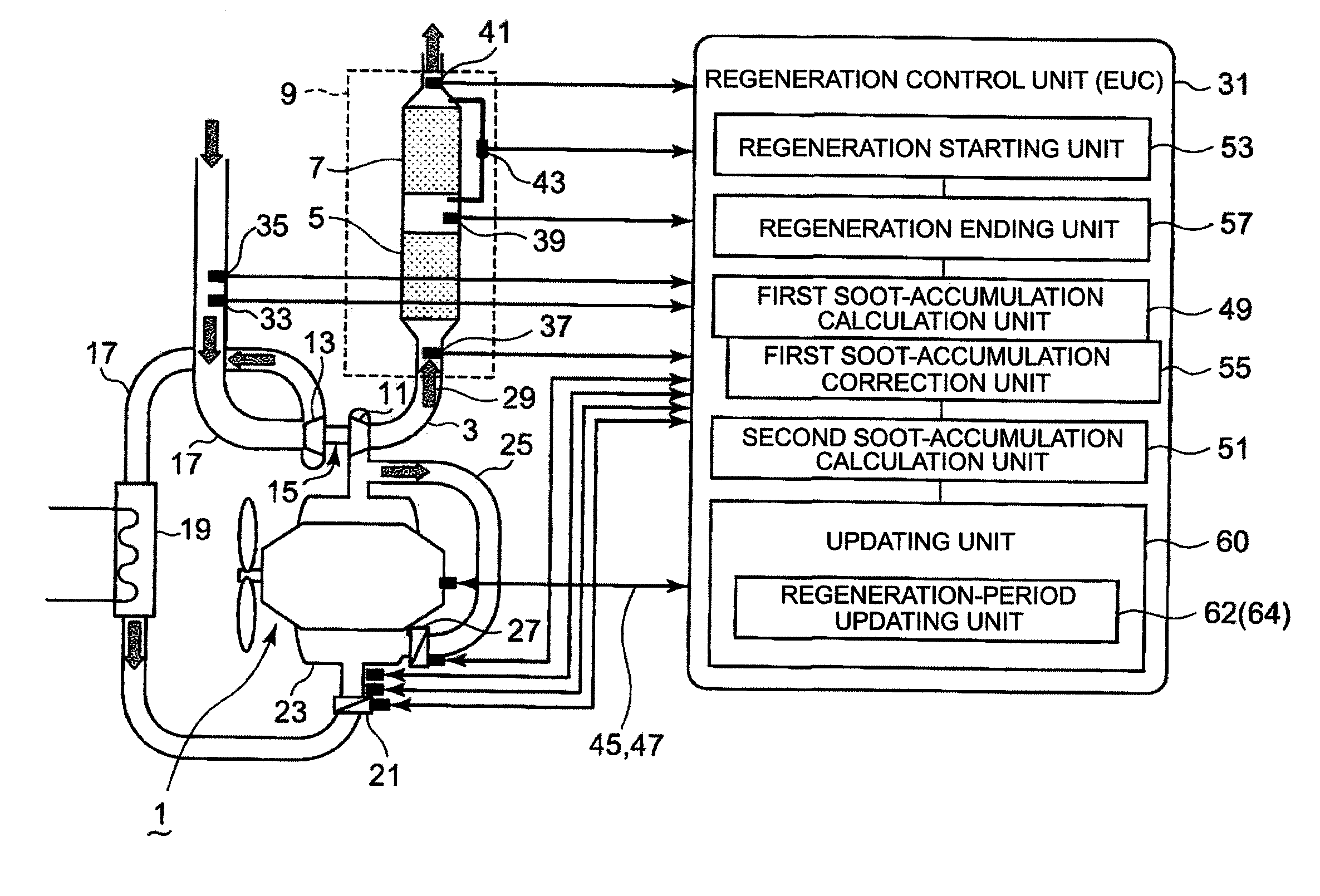
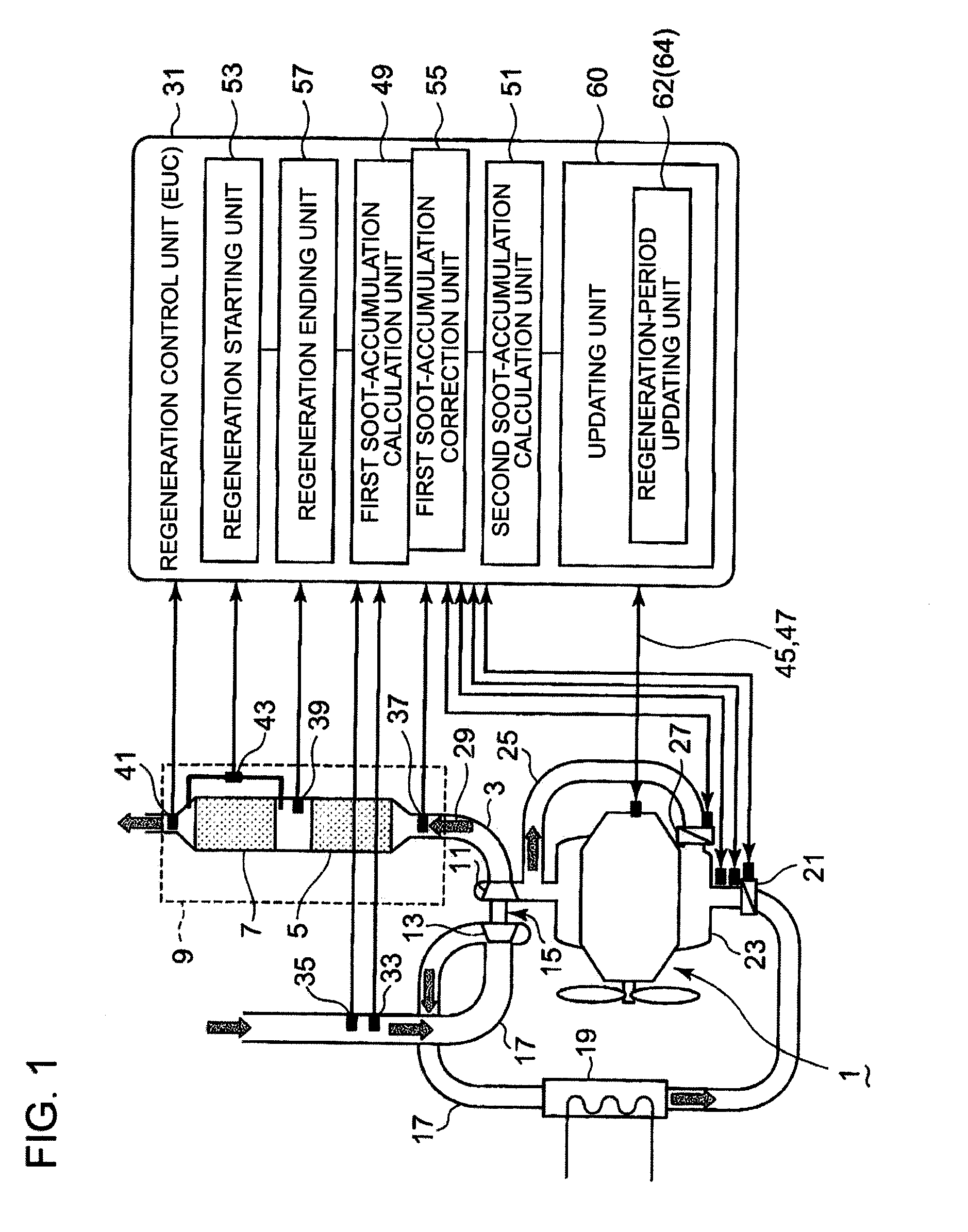
[0064]In reference to FIG. 1, explained is an exhaust gas purification apparatus for a diesel engine in relation to a first embodiment of the present invention.

[0065]As shown in FIG. 1, an exhaust-gas aftertreatment device 9 is arranged in an exhaust pipe 3 of a diesel engine (hereinafter simply called as engine) 1. The exhaust-gas aftertreatment device 9 is formed by a DOC (diesel oxidation catalyst) 5 and a DPF (diesel particulate filter) 7 arranged downstream of the DOC 5 to collect soot.

[0066]Further, an exhaust turbosupercharger 15 is arranged with an exhaust turbine 11 in the exhaust pipe 3 and a compressor 13 coaxially driven by the exhaust turbine 11. The air discharged from the compressor 13 of the exhaust turbosupercharger 15 flows through an air supply pipe 17 and enters an intercooler 19 where the air is cooled. Next, the cooled air flows through an intake throttle valve 21 where the air flow is controlled and then enters a combustion chamber from an intake manifold 23 v...

second embodiment

[0096]A second embodiment is explained in reference to FIG. 4. In the second embodiment, there are a plurality of collection stages for different amounts of soot accumulated in DPF 7.

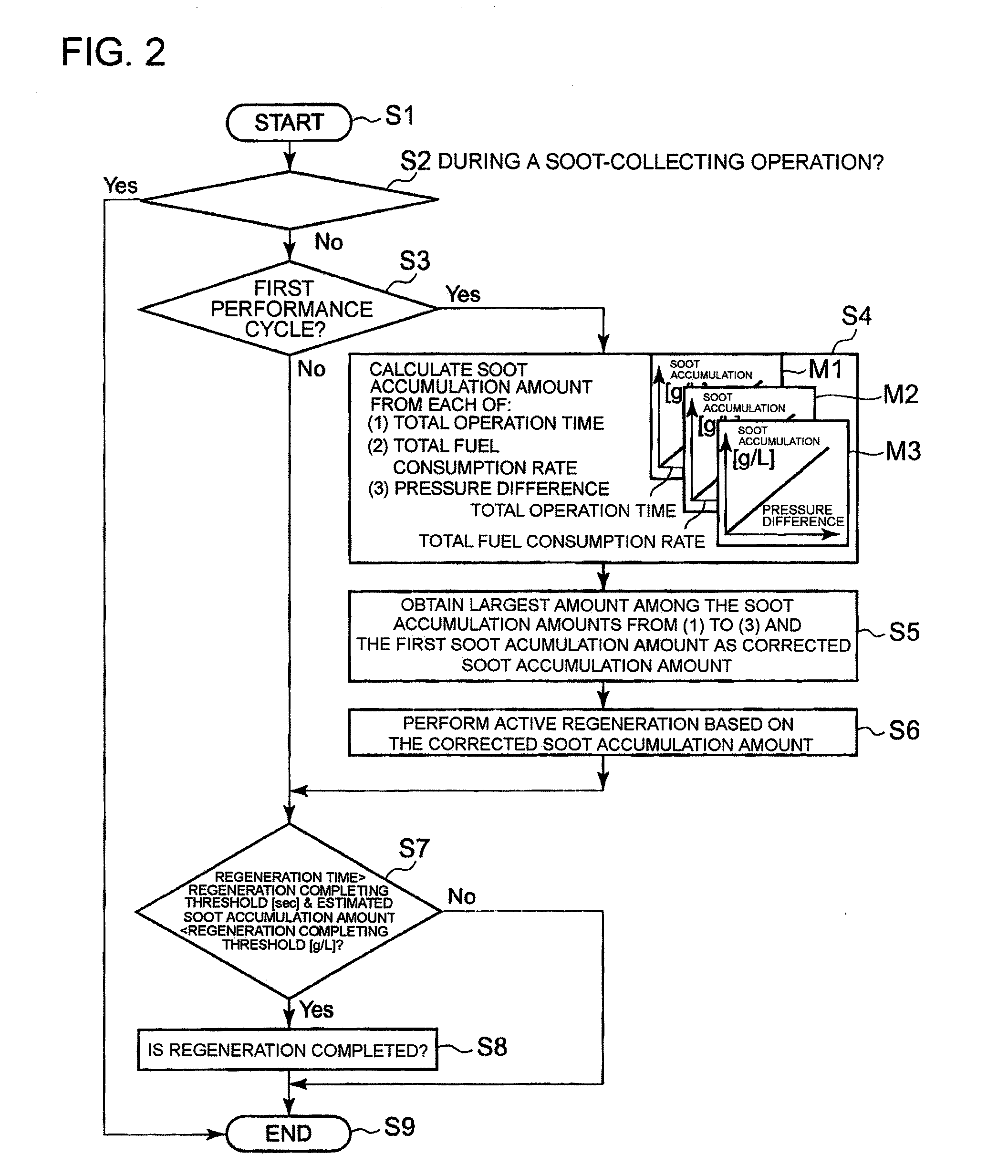
[0097]The control starts in a step S11 and then advances to a step S12 to determine whether or not it is during a soot-collecting operation. The determination step is described later in details.

[0098]If it is determined in the step S12 that the active regeneration is not started, the process advances to a step S13 to determine which collection stage it belongs to while the soot-collecting operation being performed. It is determined which collection stage the amount of soot accumulated in the DPF 7 belongs to based on the first soot accumulation amount calculated by the first soot-accumulation calculation unit 49. There are first through fifth collection stages which are divided by stage threshold values A, B, C, D, respectively.

[0099]In the second collection stage and beyond, the regeneration is permitt...

third embodiment

[0116]A third embodiment is explained in reference to FIG. 5. An updating unit 60 is provided in the third embodiment. The updating unit 60 updates, when the active regeneration is performed, count values of the total operation time and the total fuel consumption rate to a total operation time and a total fuel consumption rate which correspond to the soot accumulation amount calculated by the first soot-accumulation calculation unit 49. The updating unit 60 includes a regeneration-period updating unit 62 which updates the count values by reflecting results of the calculation during the regeneration constantly, or a stopping-period updating unit 64 which updates the count values by reflecting the calculation result when the active regeneration is stopped. The stopping of the active regeneration is explained later in the fourth embodiment. In the third embodiment, the regeneration-period updating unit 62 is explained.

[0117]In a flow chart of FIG. 5A, the process starts in a step S31 a...


PUM

PropertyMeasurementUnit
inlet temperatureaaaaaaaaaa
temperatureaaaaaaaaaa
pressureaaaaaaaaaa

Abstract

An exhaust gas purification apparatus is provided with: a first soot-accumulation calculation unit 49 which calculates a first soot accumulation amount from an operation state of the engine; a second soot-accumulation calculation unit 51 which calculates a second soot accumulation amount from a total operation time of the engine, a total fuel consumption rate, a pressure difference between front and back of the particulate filter, and the like; a first soot-accumulation correction unit 55 which corrects the first soot accumulation amount calculated by the first soot-accumulation calculation unit 49 to a value greater than the first soot-accumulation amount when the active regeneration starts based on the second soot accumulation amount calculated by the second soot-accumulation calculation unit 51; and a regeneration ending unit 57 which ends the active regeneration when, in such a case that the active regeneration starts based on the corrected soot accumulation amount, the first soot accumulation amount becomes less than a threshold value of ending the regeneration.

Description

TECHNICAL FIELD[0001]The present invention relates to an exhaust gas purification apparatus for a diesel engine, in particular to a diesel engine, which is provided with a diesel particulate filter (hereinafter called DPF) for removing soot from exhaust gas.BACKGROUND ART[0002]In emission regulations of diesel engines, reduction of soot is just as important as reduction of NOx. The DPF is known as an effective technology for this.[0003]The DPF is a diesel particulate filter. While the engine operates at low exhaust temperature, the soot keeps accumulating in the DPF. The accumulated soot is removed by filter regeneration, i.e. by actively raising the temperature to burn the accumulated soot.[0004]When estimation accuracy for estimating an amount of the soot accumulated in the DPF is low, it is hard to determine when to start or end the regeneration. This can lead to over-accumulation of the soot, resulting in adverse affect on the engine. Further, when performing the regeneration in...

Claims


Application Information

Patent Timeline
Patent Type & Authority Applications(United States)
IPC IPC(8): B01D53/94
CPCF01N9/002F01N11/005F01N2900/1606F02D2200/0812Y02T10/47F02D41/2451Y02T10/40F01N3/02B01D46/42F01N3/023
Inventor TAKAYANAGI, KO
Owner MITSUBISHI HEAVY IND ENGINE & TURBOCHARGER LTD
Why Eureka
Try Eureka