Method to Model and Program a Robotic Workcell

a workcell and robotic technology, applied in the field of robot programming methodologies, can solve the problems of increasing the time required for robot operation, increasing the cost of robotic and workcell programming, and not seeing wide acceptance of techniques, so as to reduce the time to operation of the robot

Inactive Publication Date: 2012-11-15
KAPOOR CHETAN
View PDF17 Cites 51 Cited by
  • Summary
  • Abstract
  • Description
  • Claims
  • Application Information

AI Technical Summary

Benefits of technology

[0013]I submit that each of these embodiments of my invention provides for a method of robot programming that significantly reduces the time to operation of the robot and associated workcell, the cap

Problems solved by technology

Furthermore, it is of no relevance in such systems which specific voltage levels are selected to represent each of the logic states.
However, these methods also serve to transfer additional effort to the programming and calibration of vision systems associated with the target identification system.
This technique has not s

Method used


Image

  • Method to Model and Program a Robotic Workcell
  • Method to Model and Program a Robotic Workcell
  • Method to Model and Program a Robotic Workcell

Examples


Embodiment Construction

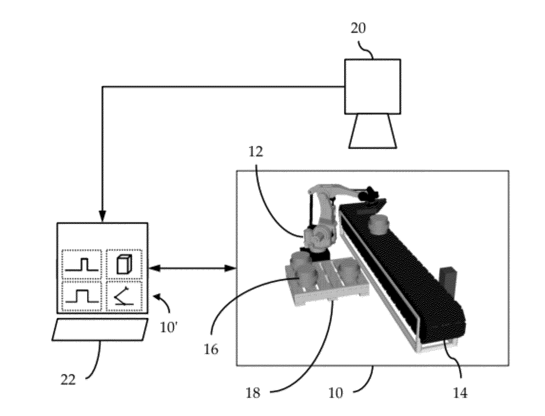
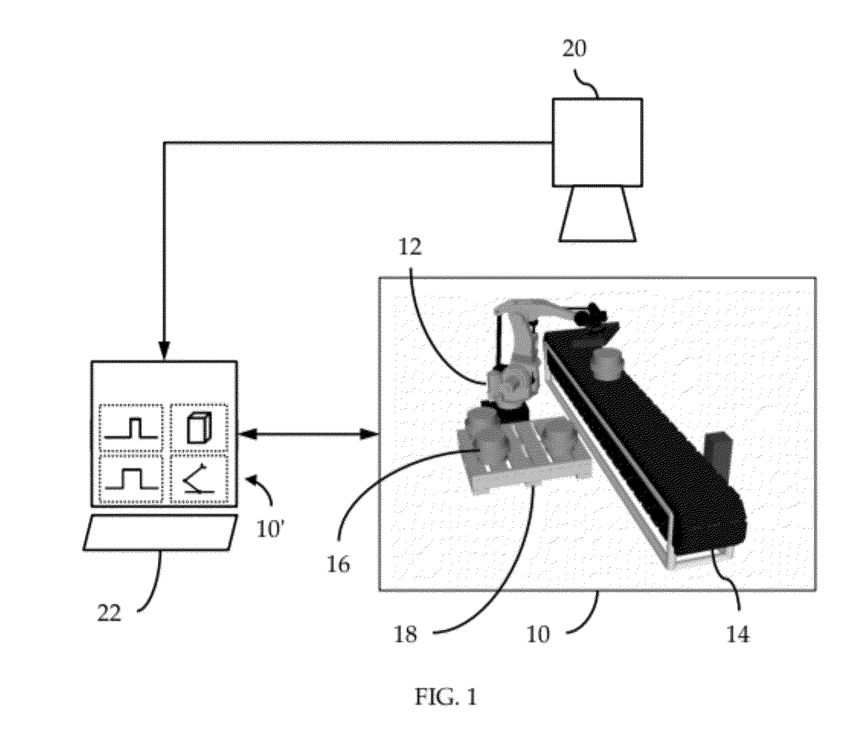
[0018]Illustrated in FIG. 1 is a typical instantiation of the types and configuration of hardware components that will comprise a fully operational, physical workcell 10. By way of example, the workcell 10 comprises a robot 12 and a peripheral device 14 adapted sequentially to convey a series of workpieces 16 from a location outside the workcell 10 into the workcell 10 for transfer by the robot 12 to a pallet 18; of course, if desired, the workcell 10 can be reconfigured such that the robot 12 sequentially transfers a series of workpieces 16 from the pallet 18 onto the peripheral device 14 for conveyance to a location outside of the workcell 10.

[0019]Associated with workcell 10 is at least one camera system 20 positioned so as continuously to provide to a robot control system 22 precise location information on each of the workpieces 16 being conveyed by the peripheral device 14 toward the robot 12. In particular, my control system 22 is specially adapted to perform a number of compu...


PUM


Abstract

An improved method to model and program a robotic workcell. Two-dimensional (2D) images of a physical workcell are captured to facilitate, in part, initial integration of any preexisting three-dimensional (3D) component models into a 3D model workcell. 3D models of other essential workcell components are synthesized and integrated into the 3D workcell model. The robot is then configured and programmed. The resultant 3D workcell model more faithfully reflects the “as-built” workcell than a traditional model that represents the “as-designed” workcell.

Description

CROSS-REFERENCE TO RELATED APPLICATIONS[0001]This application claims priority to U.S. Provisional Application Ser. No. 61 / 484,415 filed 10 May 2011 (“Parent Provisional”) and hereby claims benefit of the filing dates thereof pursuant to 37 CFR §1.78(a)(4).[0002]This application contains subject matter generally related to U.S. application Ser. No. 12 / 910,124 filed 22 Oct. 2010 (“Related Co-application”), assigned to the assignee hereof.[0003]The subject matter of the Parent Provisional and the Related Co-application (collectively, “Related References”), each in its entirety, is expressly incorporated herein by reference.FIELD OF THE INVENTION[0004]The present invention relates generally to robot programming methodologies, and, in particular, robot-programming methods in the context of workcells.BACKGROUND OF THE INVENTION[0005]In general, in the descriptions that follow, I will italicize the first occurrence of each special term of art that should be familiar to those of ordinary sk...

Claims


Application Information

Patent Timeline
IPC IPC(8): G05B19/418G06F19/00G06F17/50
CPCG05B19/41885B25J9/1671Y02P90/02
Inventor KAPOOR, CHETAN
Owner KAPOOR CHETAN
Why Eureka
Try Eureka