Optical device and method for detecting the drift of a light beam
a light beam and optical device technology, applied in the direction of optical elements, instruments, manufacturing tools, etc., can solve the problems of limited beam size of laser machining system, large distance between optical elements, and significant space requirements, and achieve good detection sensitivity
- Summary
- Abstract
- Description
- Claims
- Application Information
AI Technical Summary
Benefits of technology
Problems solved by technology
Method used
Image
Examples
Embodiment Construction
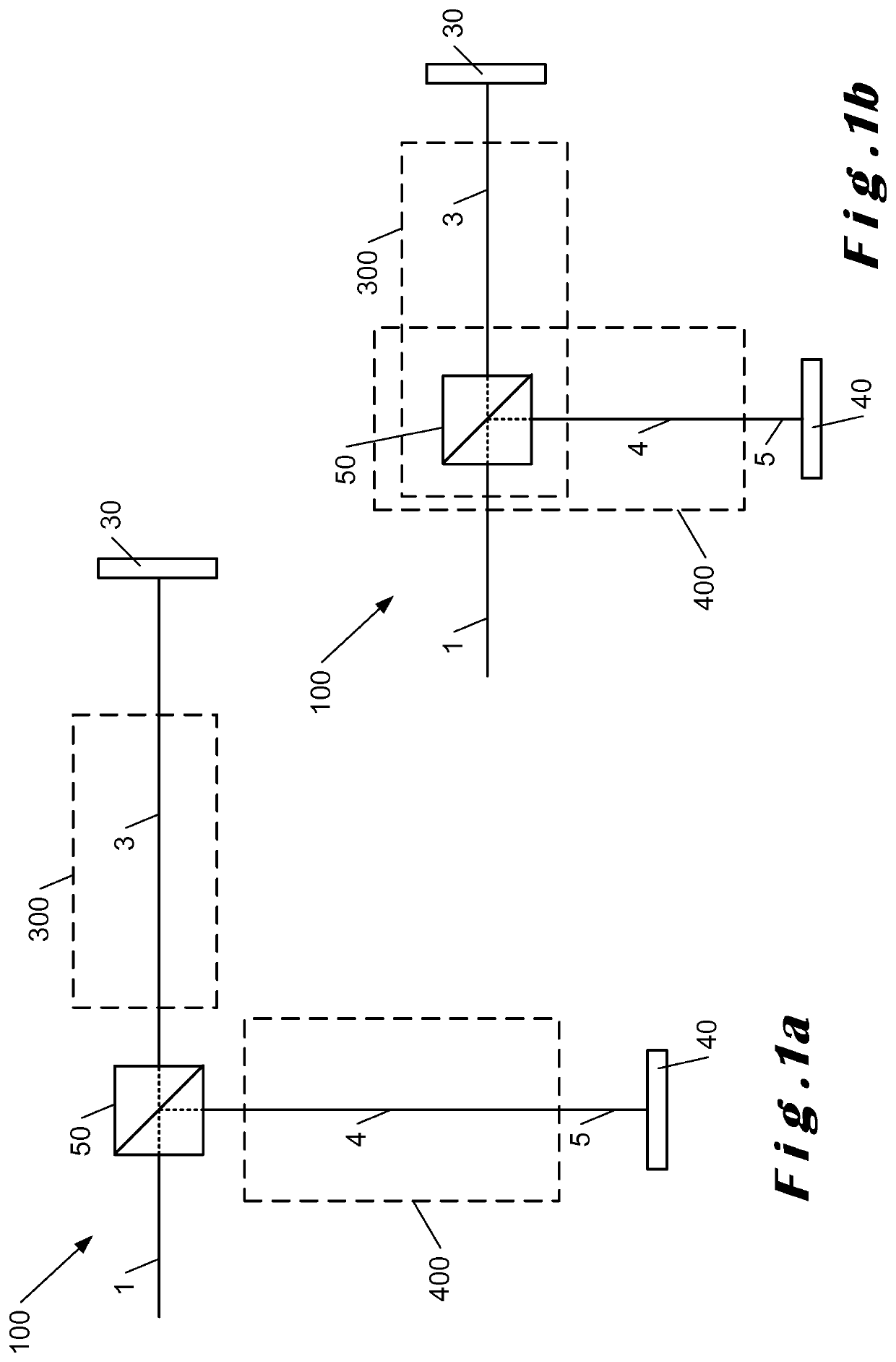
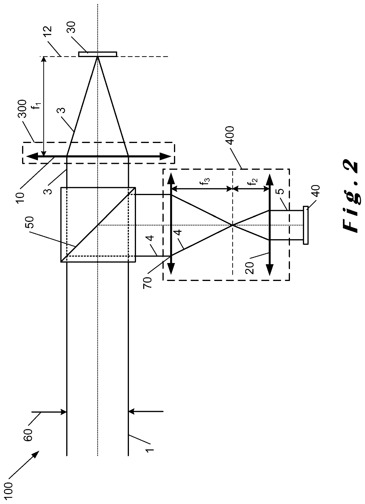
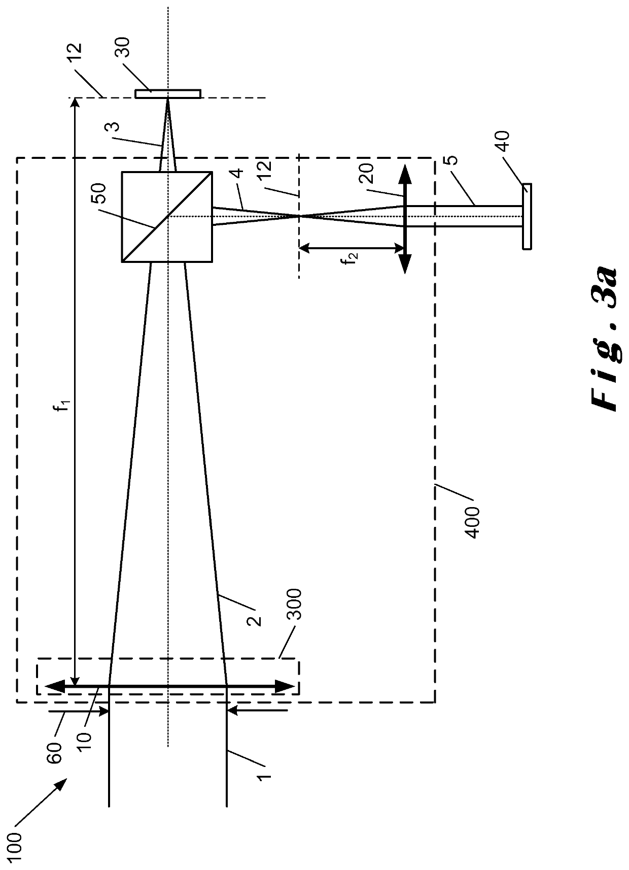
[0111]An incoming light beam 1 is for example a laser beam transmitted by a mirror of a laser machining system. The transmission by a mirror of a machining system is for example unavoidable and the system of the invention makes it possible to use the light beam transmitted by the mirror and which would be lost. Indeed, the light intensity not reflected by a mirror but transmitted is sufficient to detect a shift in position or an angular shift of a light beam. For example, for a machining laser beam with a power of 20 W reflected on a mirror, it can be reasonably estimated that this beam is transmitted with a power of about 20 mW. The light beam thus transmitted and attenuated by said mirror is then directed towards the optical device of FIG. 1a, 1b, 2, 3a or 3b.
[0112]FIG. 1a shows an example of embodiment of the device for detecting a shift of an incoming light beam 1 of a laser machining system. The incoming light beam is directed towards a beam splitter 50, separating the inciden...
PUM
| Property | Measurement | Unit |
|---|---|---|
| focal length f1 | aaaaa | aaaaa |
| focal length f1 | aaaaa | aaaaa |
| focal length f2 | aaaaa | aaaaa |
Abstract
Description
Claims
Application Information
 - R&D
- Intellectual Property
- Life Sciences
- Materials
- Tech Scout
- Unparalleled Data Quality
- Higher Quality Content
- 60% Fewer Hallucinations
Browse by: Latest US Patents, China's latest patents, Technical Efficacy Thesaurus, Application Domain, Technology Topic, Popular Technical Reports.
© 2025 PatSnap. All rights reserved.Legal|Privacy policy|Modern Slavery Act Transparency Statement|Sitemap|About US| Contact US: help@patsnap.com


