Optical device and method for detecting the drift of a light beam

a light beam and optical device technology, applied in the direction of optical elements, instruments, manufacturing tools, etc., can solve the problems of limited beam size of laser machining system, large distance between optical elements, and significant space requirements, and achieve good detection sensitivity

Active Publication Date: 2021-04-22
LASER ENG APPL
View PDF0 Cites 1 Cited by
  • Summary
  • Abstract
  • Description
  • Claims
  • Application Information

AI Technical Summary

Benefits of technology

[0004]According to a first aspect, one of the purposes of this invention is to provide a compact optical device that allows good sensitivity in detecting a lateral and / or angular shift of a light beam.
[0012]The advantage of the device of the invention for detecting the drift of a light beam is that it is particularly compact while allowing a high sensitivity for detecting an angular shift and / or detecting a shift in the position of the beam in a given plane. Indeed, this is possible thanks to the positioning of two optical matrix detectors that “look” at two different places from the same incident laser beam. For example, the leakage of the incident laser beam is focused and then, during its separated focusing in two to go to the two optical matrix detectors. One of the two optical matrix detectors is placed at the focal point, the other looks at the lens through a second lens that collimates the beam. In another example, the leakage of the incident laser is split in two and then a first beam is focused on a matrix optical detector and a second beam is passed through an afocal module to another detector. The afocal module preferably allows a control of the size of the second beam projected on the detector. Optically this corresponds to an infinite measurement and a local measurement. The device of the invention therefore makes it possible to create a virtual large distance between the two optical matrix sensors over a very small area, thus offering very high measurement accuracy with relatively short optical paths to the two optical matrix sensors. The optical device for detecting the drift of a light beam is therefore both compact and highly sensitive to direction or angle shifts, and position shift of a laser beam.
[0014]Another advantage of the system over the prior art systems is that the prior art systems generally include a free propagating channel, i.e. without an afocal module. Such a system could be as compact as the device of the invention by folding it back, i. e. by using many mirrors to ensure a sufficiently long free propagation. Often the prior art systems include either two free propagating channels or a channel with a converging lens on one channel and free propagating on the other. The prior art systems mean that the beam size of a laser machining system is limited by the size of the matrix detectors used. Detectors with a large detection surface can be used but at much higher costs. The optical device of the invention allows, thanks to the afocal module, to look at a large beam on a small detector since it reduces its size. The system of the invention therefore allows the use of smaller, less expensive detectors . . . .
[0022]The device of the invention allows to create a large distance between the two optical matrix detectors on a very small area, i.e. with relatively short optical paths between the first focusing means and the two optical detectors, the device of the invention allows an infinite measurement and a local measurement. This particularity of the optical device of the invention is possible thanks in particular to the positioning of the second focusing means with respect to the first focusing means such that their distance to the optical centre is equal to f1+f2. This makes it possible to obtain a compact optical device while offering a very high measurement accuracy.
[0025]The first focusing means (first lens) is common to channels 1 and 2. The second focusing means allows the entrance pupil to be imaged on the second light beam matrix detection means. The first light beam matrix detection means makes it possible to detect the lateral position of the beam in a plane that is (theoretically) reflected to infinity. The second light beam matrix detection means is used to detect the beam position at the level of the plane of the entrance pupil.
[0073]The invention allows a very fast automatic alignment of the light beam because the optical device for detecting the drift of the light beam is very fast and allows, thanks to its high sensitivity, a very fast servo-controlling in angular and / or lateral position because it requires very few iterations of servo-control measurement to achieve an aligned light beam. Indeed, the prior art optical devices having the compactness of the device according to the first aspect of the invention do not allow good sensitivity and therefore require more iterations of servo-control measurement to achieve an aligned light beam. This also provides an optical system for the automatic alignment of a fast and compact light beam thanks to the compact and sensitive drift detection device according to the first aspect of the invention. The optical system for the automatic alignment of a light beam of the invention is preferably used in a laser machining machine for the machining of materials. The interest of the device and system according to the first and second aspects of the invention is to allow the manufacture of laser machining machines that are more compact and easier to build.

Problems solved by technology

A disadvantage of this stabilization device is that it requires large distances between the optical elements in order to have sufficient resolution of the lateral position shift and in particular the angular position shift.
The problem with the prior art light beam drift detection devices is that in order to provide satisfactory sensitivity, they require large optical distances resulting in significant space requirements.
The prior art systems mean that the beam size of a laser machining system is limited by the size of the matrix detectors used.
Detectors with a large detection surface can be used but at much higher costs.
Indeed, the prior art optical devices having the compactness of the device according to the first aspect of the invention do not allow good sensitivity and therefore require more iterations of servo-control measurement to achieve an aligned light beam.

Method used


Image

  • Optical device and method for detecting the drift of a light beam
  • Optical device and method for detecting the drift of a light beam
  • Optical device and method for detecting the drift of a light beam

Examples


Embodiment Construction

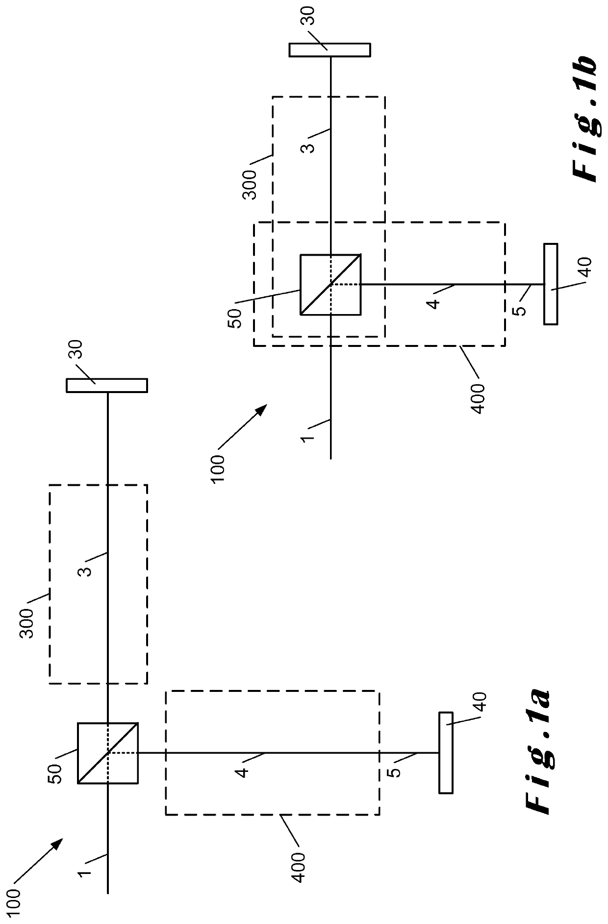
[0102]An incoming light beam 1 is for example a laser beam transmitted by a mirror of a laser machining system. The transmission by a mirror of a machining system is for example unavoidable and the system of the invention makes it possible to use the light beam transmitted by the mirror and which would be lost. Indeed, the light intensity not reflected by a mirror but transmitted is sufficient to detect a shift in position or an angular shift of a light beam. For example, for a machining laser beam with a power of 20 W reflected on a mirror, it can be reasonably estimated that this beam is transmitted with a power of about 20 mW. The light beam thus transmitted and attenuated by said mirror is then directed towards the optical device of FIG. 1a, 1b, 2, 3a or 3b.

[0103]FIG. 1a shows an example of embodiment of the device for detecting a shift of an incoming light beam 1 of a laser machining system. The incoming light beam is directed towards a beam splitter 50, separating the inciden...


PUM

PropertyMeasurementUnit
distanceaaaaaaaaaa
distanceaaaaaaaaaa
distanceaaaaaaaaaa

Abstract

An optical device for detecting the drift of a light beam of a laser machining system includes a beam splitter for obtaining a first light beam along a first optical path and a second light beam along a second optical path. The optical device further includes a focal module positioned at least partially along the first optical path to obtain a focused light beam that is directed towards a first light beam matrix detection means positioned in a focusing plane associated with the focal module. The optical device also includes an afocal module positioned at least partially along the second optical path to obtain a collimated light beam that is directed towards a second light beam matrix detection means.

Description

TECHNICAL FIELD[0001]According to a first aspect, the invention refers to an optical device for detecting the drift of a light beam. According to a second aspect, the invention refers to an optical system for the automatic alignment of a light beam. According to a third aspect, the invention refers to a method for positioning optical elements for the design of an optical device according to the first aspect.PRIOR ART[0002]U.S. Pat. No. 6,014,206 discloses an optical stabilization device for automatically adjusting the angular and lateral position of a light beam. The angular and lateral position of a light beam is detected by a measurement of the focused light beam and by an infinite measurement. A disadvantage of this stabilization device is that it requires large distances between the optical elements in order to have sufficient resolution of the lateral position shift and in particular the angular position shift.[0003]The problem with the prior art light beam drift detection devi...

Claims


Application Information

Patent Timeline
Patent Type & Authority Applications(United States)
IPC IPC(8): B23K26/04G02B27/10G01B11/27B23K26/70
CPCB23K26/043G02B27/10G02B19/0009B23K26/705G01B11/272
Inventor ESTIVAL, SÉBASTIENMARTIN, PAUL-ETIENNE
Owner LASER ENG APPL
Why Eureka
Try Eureka