Inverter generator control apparatus

a technology of inverter generators and control apparatuses, which is applied in the direction of electric generator control, mechanical apparatus, machines/engines, etc., can solve the problems of a great burden on the operator and a troublesome operator, and achieve the effect of reducing the burden on the operator

Inactive Publication Date: 2012-11-22
HONDA MOTOR CO LTD
View PDF36 Cites 11 Cited by
  • Summary
  • Abstract
  • Description
  • Claims
  • Application Information

AI Technical Summary

Benefits of technology

[0006]An object of embodiments of this invention is therefore to overcome the foregoing problems by providing an inverter generator control apparatus that stops outputting to an electric load when the generator is under the overload condition, thereby protecting the electric load, etc., while making it easy to restart the outputting after the stop so as to mitigate a burden on the operator.

Problems solved by technology

However, when it is configured as in the reference, in order to restart the outputting to the electric load, the operator (user) needs to restart the stopped engine after eliminating the overload condition by reducing the electric load and it is troublesome for the operator.
Further, in the case where a start-up operation of the engine of the generator is carried out manually through a recoil starter or the like, it is a great burden on the operator to conduct the start-up operation every time to restart the outputting.

Method used


Image

  • Inverter generator control apparatus
  • Inverter generator control apparatus
  • Inverter generator control apparatus

Examples


first embodiment

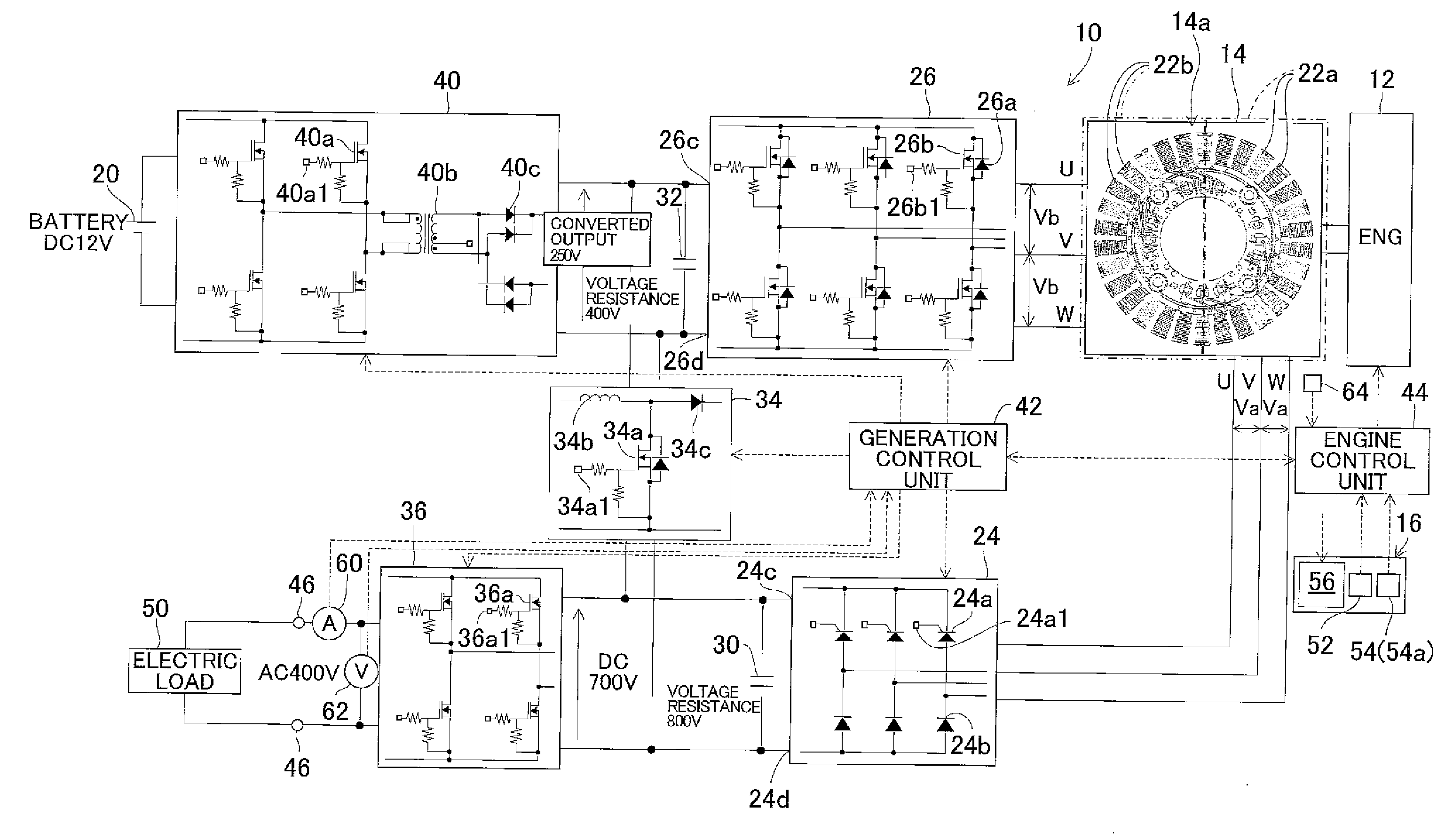
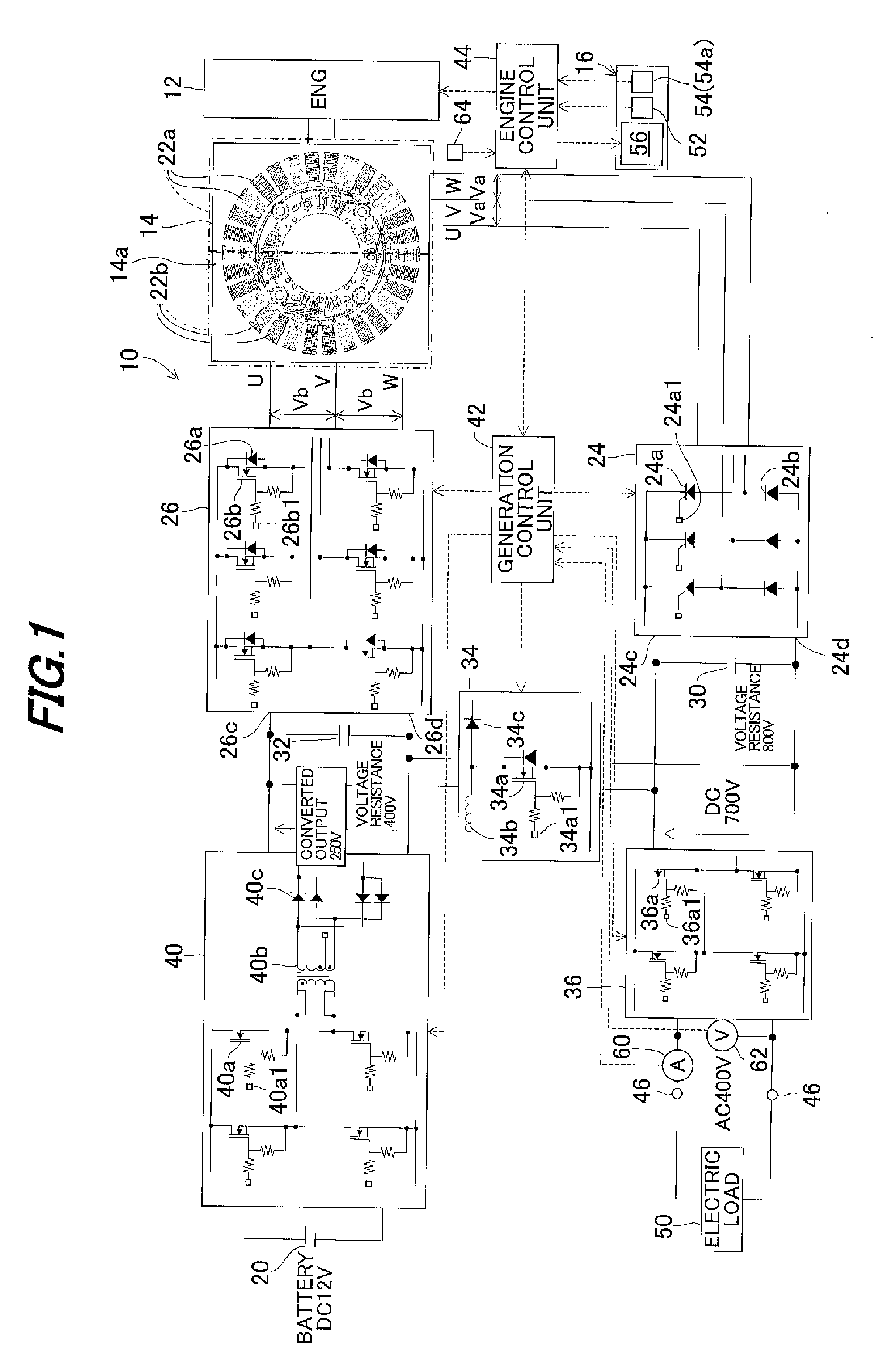
[0020]FIG. 1 is an overall block diagram showing an inverter generator control apparatus according to the invention.

[0021]Before starting the explanation on FIG. 1, the configuration of a conventional inverter generator control apparatus will be explained. FIG. 9 is an overall block diagram similar to FIG. 1, but showing an inverter generator control apparatus according to a conventional technique.

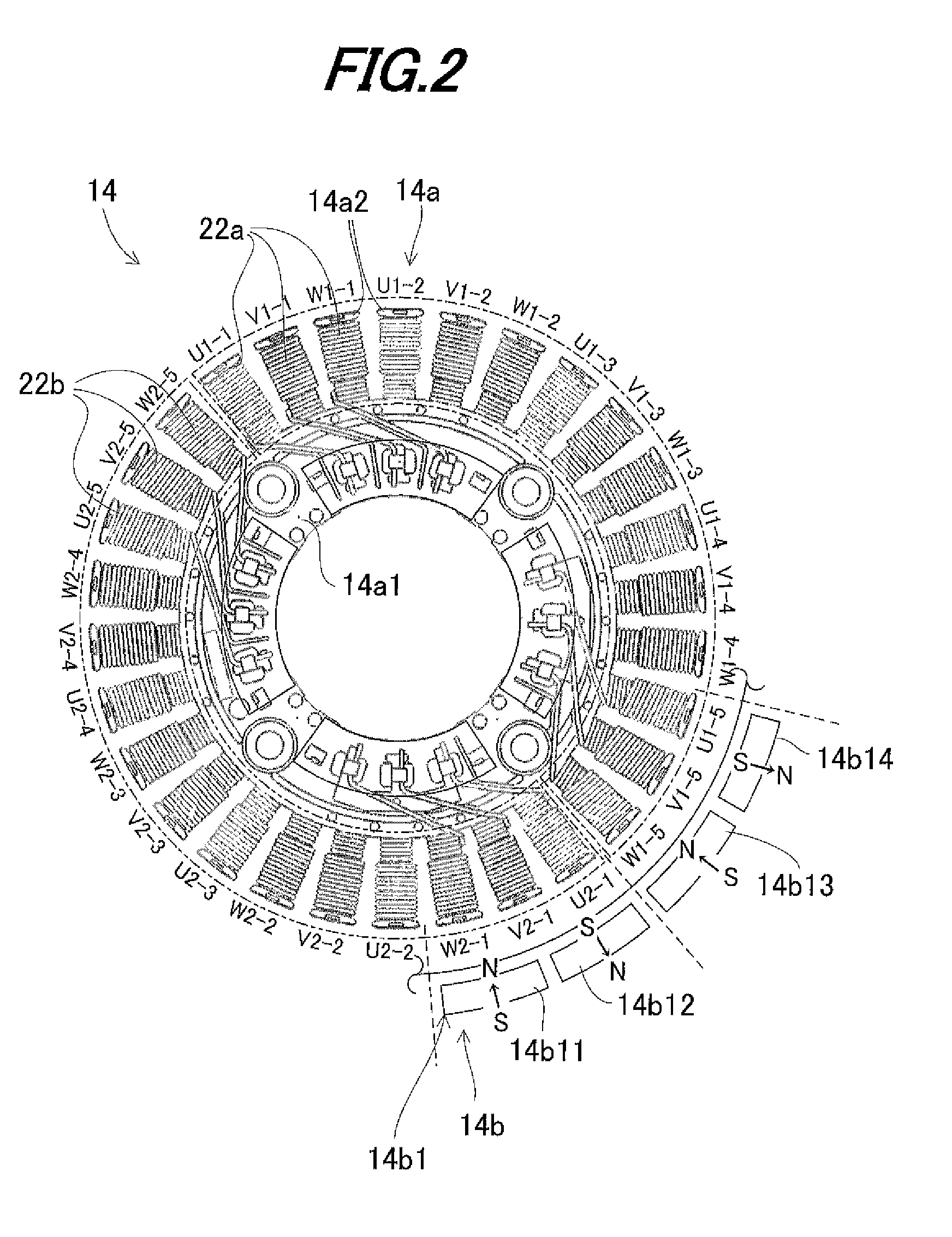
[0022]As shown in FIG. 9, an inverter generator 100 is equipped with a generator unit (starter generator) 104 driven by an engine 102 and has a rated output voltage of AC 400V (maximum voltage: 750V). The generator unit 104 is wound by an output winding 106 and a line-to-line voltage V1 to be generated at the output winding 106 (i.e., an output voltage of the generator unit 104) is 500V that is defined by the rated output voltage of the inverter generator 100. The line-to-line voltage defined in accordance with the rated output voltage of the generator is hereinafter called the “defined li...

second embodiment

[0094]An inverter generator control apparatus according to this invention will now be explained.

[0095]FIG. 5 is a set of plan views showing the control panel 16 of the inverter generator control apparatus according to the second embodiment.

[0096]The explanation of the second embodiment will focus on the points of difference from the first embodiment. In the second embodiment, the release switch 54 is constituted of, in place of the volume switch, a push switch of momentary type that is installed to be manually operated by the operator, as shown in FIG. 5. The release switch (assigned by 54a in the second embodiment) outputs to the engine control unit 44 an ON signal when manipulated (pressed) by the operator and an OFF signal when not manipulated.

[0097]FIG. 6 is a flowchart similar to FIG. 4, but showing the operation of the engine control unit 44, i.e., the operation when an overload condition is detected. Note that steps of the same operations as in FIG. 4 are assigned by the same...

third embodiment

[0103]An inverter generator control apparatus according to this invention will now be explained.

[0104]The third embodiment is an alternative example of the first embodiment. It is configured so that the release switch 54 can be used not only to release the outputting stop condition established in response to detection of the overload condition, but also to temporarily stop or suspend the outputting to the electric load 50 upon manipulation during the normal operation.

[0105]FIG. 7 is a flowchart similar to FIG. 4, but showing the operation of the engine control unit 44 of the inverter generator control apparatus according to the third embodiment.

[0106]The explanation will be made with focus on the points of difference from the flowchart in the first embodiment. The processing of S10 to S34 is conducted similarly to that in the first embodiment. When the result in S10 is negative, i.e., when the overload condition is not detected and it is determined to be in the normal operation, the...


PUM


Abstract

In a control apparatus for an inverter generator having a generator unit driven by an engine, a converter connected to the generator unit to convert an alternating current from the generator unit to a direct current, and an inverter connected to the converter to invert the direct current from the converter to an alternating current and output it to an electric load, it is configured to detect an overload condition based on the alternating current from the inverter to the electric load; stop outputting from the inverter to the electric load with the engine being kept operating when the overload condition is detected; output a release command to release a stop condition where the outputting to the electric load is stopped upon manipulation by an operator; and restart the outputting to the electric load by releasing the stop condition when the release command is outputted.

Description

BACKGROUND OF THE INVENTION[0001]1. Technical Field[0002]Embodiments of the invention relate to an inverter generator control apparatus, particularly to an apparatus for controlling an inverter generator equipped with a generator unit driven by an engine.[0003]2. Background Art[0004]Conventionally, in an apparatus for controlling an inverter generator equipped with a generator unit driven by an engine, there is proposed a technique in which, when an electric load connected to the generator becomes excessive so that an overload condition is detected, the engine operation is stopped to stop outputting to the electric load, thereby protecting the electric load and components (such as an electric circuit, etc.) constituting the generator, as taught, for example, by Japanese Patent No. 3464169 (a paragraph [0075], etc.).SUMMARY[0005]However, when it is configured as in the reference, in order to restart the outputting to the electric load, the operator (user) needs to restart the stopped...

Claims


Application Information

Patent Timeline
Patent Type & Authority Applications(United States)
IPC IPC(8): H02P9/04
CPCF02B63/04H02P9/107H02P9/006H02P27/08
Inventor YAMAMURA, YOICHIHASHIMOTO, SHOJI
Owner HONDA MOTOR CO LTD
Why Eureka
Try Eureka