Multiple-way ring cavity power combiner and divider

a multi-way ring cavity, power combiner technology, applied in the direction of coupling devices, basic electric elements, waveguide type devices, etc., can solve the problems of limited output power, various limitations of power amplifier technologies, limited bandwidth, etc., and achieve the effect of sacrificing performan

Inactive Publication Date: 2012-11-22
CITY UNIVERSITY OF HONG KONG
View PDF5 Cites 14 Cited by
  • Summary
  • Abstract
  • Description
  • Claims
  • Application Information

AI Technical Summary

Benefits of technology

[0009]In various embodiments, the disclosed subject matter provides multiple-way ring cavity power combiners and power dividers. In an aspect, the disclosed subject matter provides power combiners and power dividers that can accommodate increasing numbers of ports without sacrificing performance. For example, disclosed embodiments provide multiple-way ring cavity power divider (e.g., power divider and / or power combiner) with UWB performance that can provide large numbers (e.g., greater than thirty) of power-dividing ports (e.g., power dividing and / or power combining ports).

Problems solved by technology

However, power amplifier technologies can suffer from various limitations such as, for example, limited bandwidth, limited output power, excessive losses, inconvenient or unfortunate sizing or configuration, etc.
For example, an amplifier for amplifying wireless signals can have the limitation of a low output power level as previously mentioned.
However, conventional broadband power-combining techniques for the design of broadband high-power SSPAs demonstrate that challenges remain.
Nonetheless, while such topologies can facilitate providing broadband capability, low loss, good heat sinking capability, and ease of fabrication, practical limitations such as size and performance limitations can limit the number of ports that can be provided in radial waveguide spatial power combiners.
For example, with an increasing number of power-dividing ports, the radius of a radial waveguide or conical line will increase, which can cause higher order modes in the radial waveguide or conical line power dividing cavity due to discontinuities, and which can be difficult or impractical to suppress effectively.
As a result, beyond this conventional limitation the performance of these types of power dividers can deteriorate due to the higher order modes.

Method used


Image

  • Multiple-way ring cavity power combiner and divider
  • Multiple-way ring cavity power combiner and divider
  • Multiple-way ring cavity power combiner and divider

Examples


Embodiment Construction

Overview

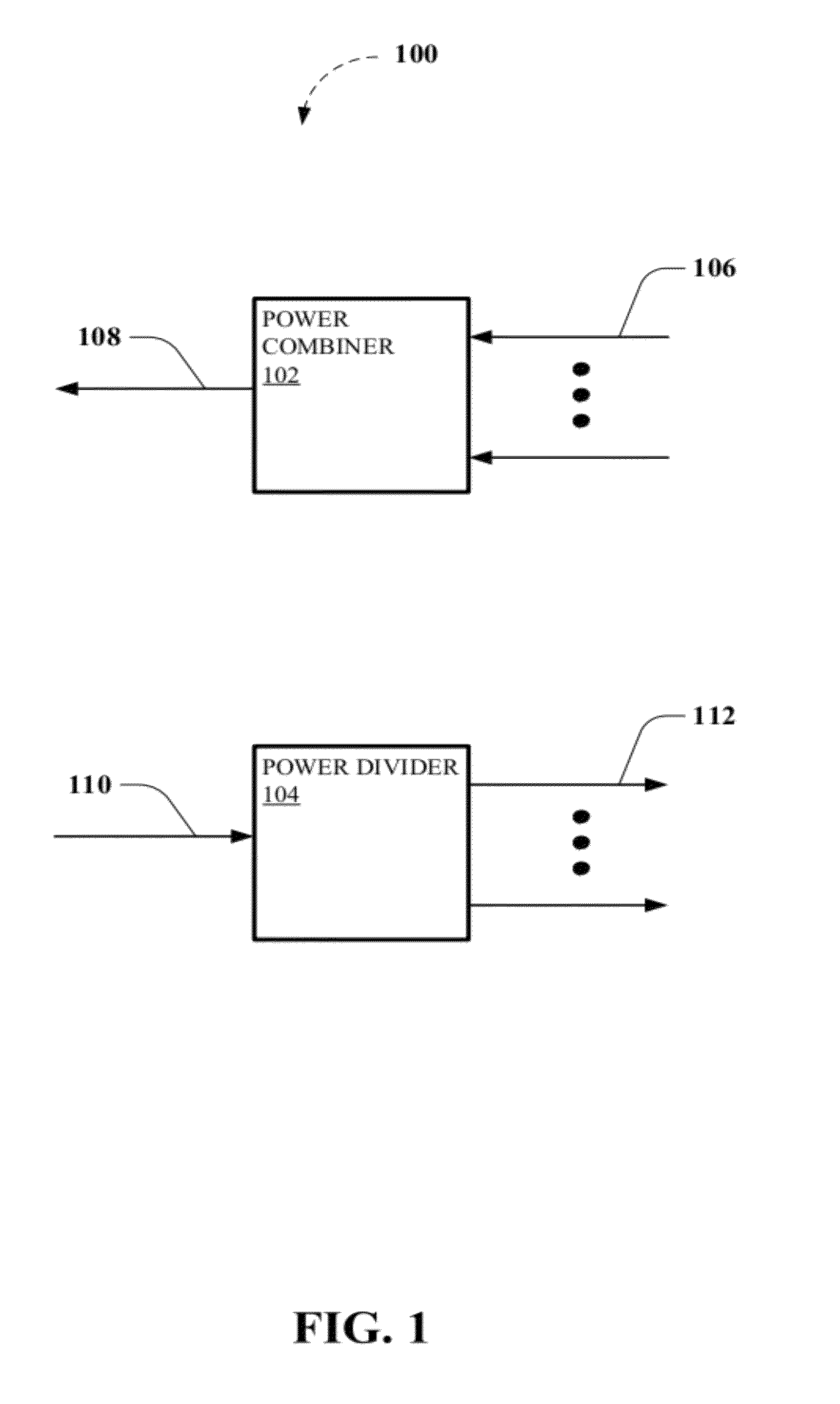
[0023]As used herein, the terms “power divider” and “power combiner” are intended to refer to a component that can be used to facilitate dividing an input signal into multiple output signals and / or combining multiple input signals into a combined output signal, respectively. It can be understood that the terms “power divider” and “power combiner” could be used interchangeably, depending on such things as context of use, configuration, design parameters, and so on, for example, to refer to the component itself, which can facilitate dividing an input signal and / or combining multiple input signals.

[0024]In addition, various general references are made herein to Ultra-Wideband (UWB) in the context of describing disclosed embodiments. For instance, UWB can typically refer to radio technologies having bandwidth exceeding the lesser of 500 MegaHertz (MHz) or 20% of the arithmetic center frequency, according to the Federal Communications Commission (FCC). For instance, the FCC autho...


PUM


Abstract

Multiple-way ring cavity power combiners and power dividers are disclosed. In one aspect, the disclosed ring cavity power combiners and power dividers can support a large number of devices by providing a large number of power-combining or power-dividing ports. In another aspect, the disclosed embodiments describe implementations employing a ring cavity that result in demonstrated performance characteristics suitable for UWB applications. Advantages provided include suppressing higher order modes and low losses among other advantages.

Description

FIELD OF THE INVENTION[0001]The subject disclosure is directed to power combining and power dividing and, more specifically, relates to multiple-way ring cavity power combiners and power dividers.BACKGROUND OF THE INVENTION[0002]Broadband solid-state power amplifiers (SSPA) with high power and high efficiency are of interest for many radio frequency (RF) applications as an attractive alternative to vacuum tube technologies. For instance, applications such as ultra-wideband (UWB) communication systems, satellite communication systems, commercial communications, and radar transmitters, are but a few systems that can benefit from high power and high efficiency broadband SSPAs. However, power amplifier technologies can suffer from various limitations such as, for example, limited bandwidth, limited output power, excessive losses, inconvenient or unfortunate sizing or configuration, etc. Power combining can be employed to overcome many of these limitations, but in certain instances, it m...

Claims


Application Information

Patent Timeline
Patent Type & Authority Applications(United States)
IPC IPC(8): H01P5/12
CPCH01P5/12H01P5/103
Inventor SONG, KAIJUNQUAN, XUE
Owner CITY UNIVERSITY OF HONG KONG
Why Eureka
Try Eureka