
Noise Blanking for Capacitive Touch Displays

Active Publication Date: 2012-11-22
PIXART IMAGING INC
View PDF5 Cites 18 Cited by
  • Summary
  • Abstract
  • Description
  • Claims
  • Application Information

AI Technical Summary

Benefits of technology

[0005]According to one embodiment, there is provided a capacitive touchscreen or touch panel system comprising a touchscreen comprising a first plurality of electrically conductive drive electrodes arranged in rows or columns, and a second plurality of electrically conductive sense electrodes arranged in rows or columns arranged at an angle with respect to the rows or columns of the first plurality of electrodes, mutual capacitances existing between the first and second pluralities of electrodes at locations where the first and second pluralities of electrodes intersect, the mutual capacitances changing in the presence of one or more fingers of a user or touch devices brought into proximity thereto, drive circuitry operably connected to the first plurality of drive electrodes, sense circuitry operably connected to the second plurality of sense electrodes and configured to sense input signals therefrom, and a controller operably connected to the first plurali

Problems solved by technology

When the linear digital filters normally present in the circuitry that processes the digitized signals encounter impulsive noise, the filters typically respond by “ringing”.
This response may disrupt normal operation for the duration of the ringing, by masking underlying touch signals, and / or by providing signals indicating non-existent i.e. false touches.
Either outcome is clearly undesirable for the user.

Method used


Image

  • Noise Blanking for Capacitive Touch Displays
  • Noise Blanking for Capacitive Touch Displays
  • Noise Blanking for Capacitive Touch Displays

Examples


Embodiment Construction

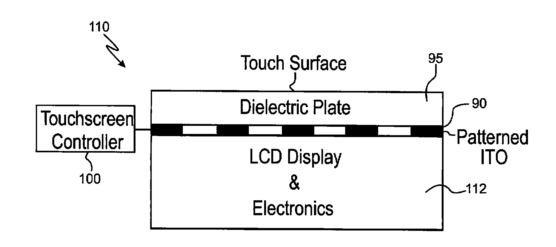
[0019]As illustrated in FIG. 1, a capacitive touchscreen system 110 typically consists of an underlying LCD or OLED display 112, an overlying touch-sensitive panel or touchscreen 90, a protective cover or dielectric plate 95 disposed over the touchscreen 90, and a touchscreen controller, micro-processor, application specific integrated circuit (“ASIC”) or CPU 100. Note that image displays other than LCDs or OLEDs may be disposed beneath touchscreen 90.

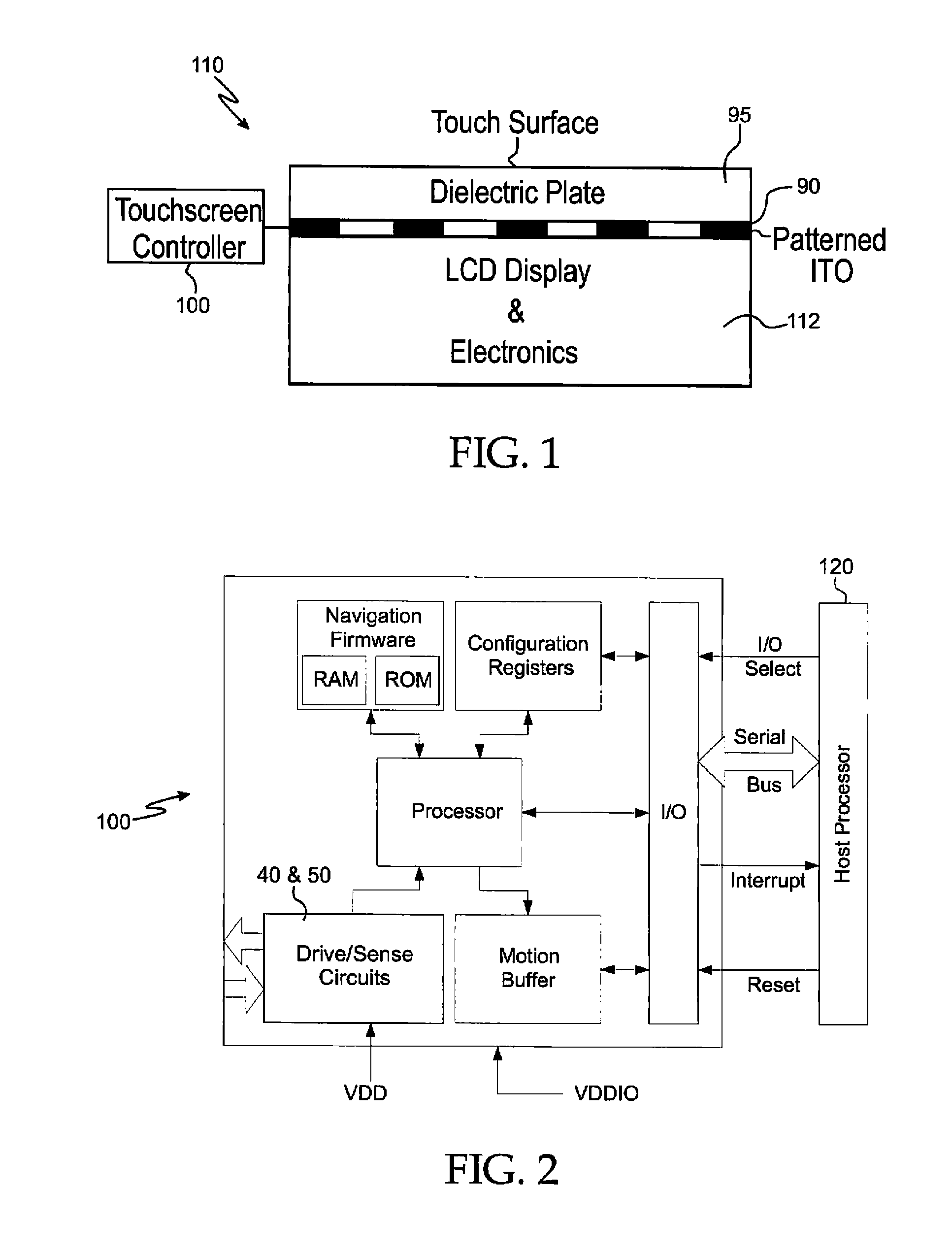
[0020]FIG. 2 shows a block diagram of one embodiment of a touchscreen controller 100. In one embodiment, touchscreen controller 100 may be an Avago Technologies™ AMRI-5000 ASIC or chip 100 modified in accordance with the teachings presented herein. In one embodiment, touchscreen controller is a low-power capacitive touch-panel controller designed to provide a touchscreen system with high-accuracy, on-screen navigation.

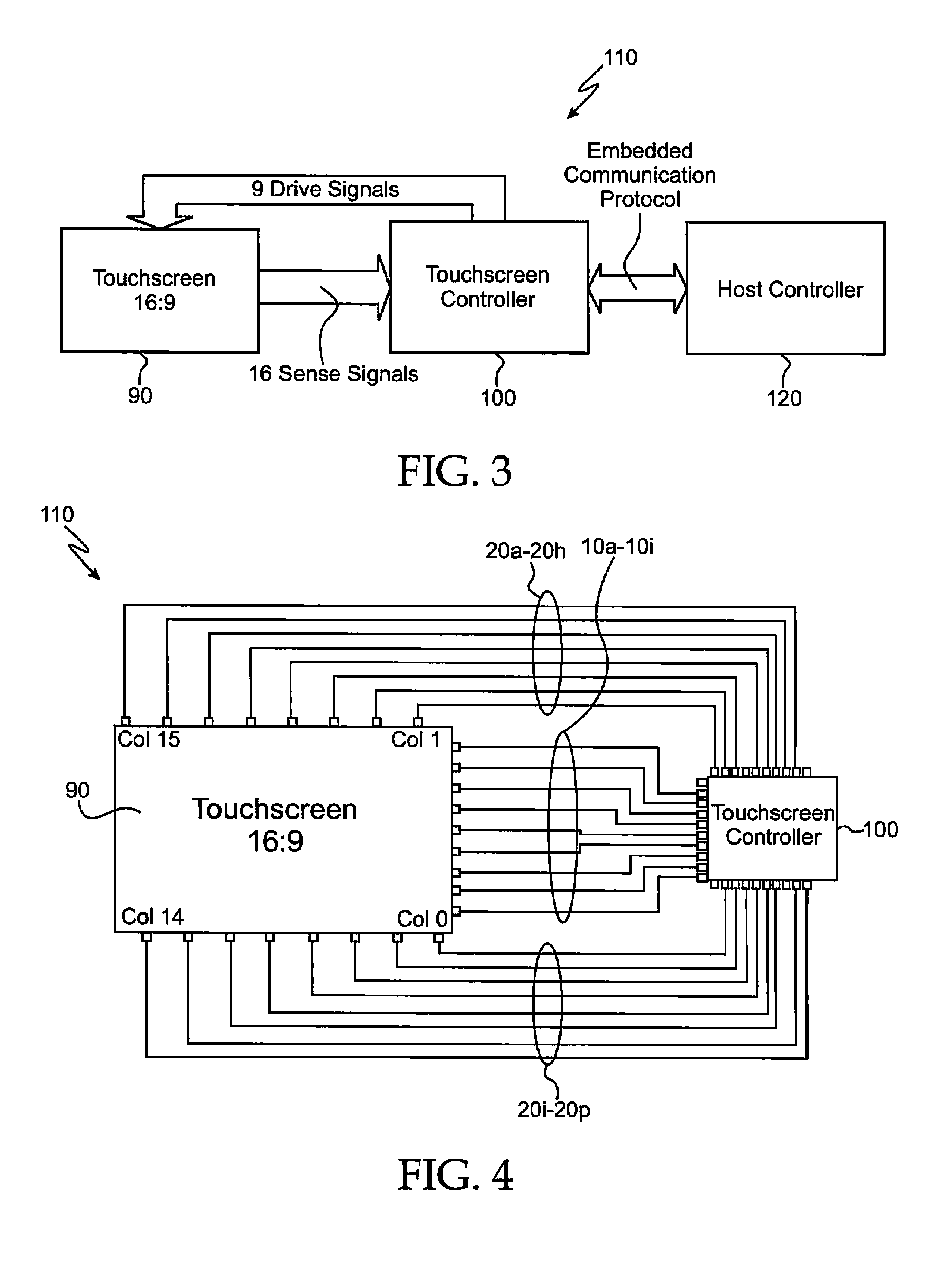
[0021]Capacitive touchscreens or touch panels 90 shown in FIGS. 3 and 4 can be formed by applying a conductive material...


PUM


Abstract

Disclosed are various embodiments of a capacitive touchscreen or touch panel system comprising a controller operably connected to a first plurality of drive electrodes and a second plurality of sense electrodes. The controller includes a noise disruption detector circuit, a user noise source detector / anticipator circuit, clock control logic circuitry operably connected to the noise disruption detector circuit and to the user noise source detector / anticipator circuit, at least one static-clocked digital filter circuit operably connected to and controlled by the clock control logic circuitry, a central processing unit (CPU) operably connected to the clock control logic circuitry, firmware operably connected to the CPU; and touch position circuitry configured to deliver signals indicative of touch positions on the touchscreen to a host controller. The controller is configured to employ at least one of the CPU and the firmware to cause the clock control logic circuitry to inhibit operation of the digital filter circuit in response to a signal representative of excessive noise levels being provided by either the noise disruption detector circuit or the user noise source detector / anticipator circuit.

Description

FIELD OF THE INVENTION[0001]Various embodiments of the invention described herein relate to the field of touchscreen or touchpad systems, devices, components and methods configured to detect touches on a touchscreen or touch panel using capacitive sensing techniques, and to provide digitized output signals indicative of such touch positions.BACKGROUND[0002]Controllers for touchscreen devices send the position-dependent signals generated by the touchscreens to analog to digital converters (ADCs) to be digitized before further processing, including digital filtering, is carried out, to extract the positional information of interest. Touchscreen devices are often operated in environments where large amplitude pulses or bursts of RF noise may be encountered. Such impulsive RF noise events may be periodic or aperiodic, with switching power supplies or fluorescent lighting systems being examples of possible sources of the periodic type, and cell phone transmission events being possible so...

Claims


Application Information

Patent Timeline
IPC IPC(8): G06F3/045
CPCG06F3/0418G06F3/044G06F3/04182G06F3/0443
Inventor CRANDALL, KENNETHBROSNAN, MICHAELLI, SAM SEN
Owner PIXART IMAGING INC
Learn More