
Method of communication

a communication method and communication technology, applied in the field of communication methods, can solve the problems of spectral efficiency loss of relaying protocols, restrictions on the transmit power of transmitters, etc., and achieve the effects of reducing inter-cell interference, reducing bit error rate, and reducing co-channel interference (cci)

Inactive Publication Date: 2012-11-22
AGENCY FOR SCI TECH & RES
View PDF8 Cites 9 Cited by
  • Summary
  • Abstract
  • Description
  • Claims
  • Application Information

AI Technical Summary

Benefits of technology

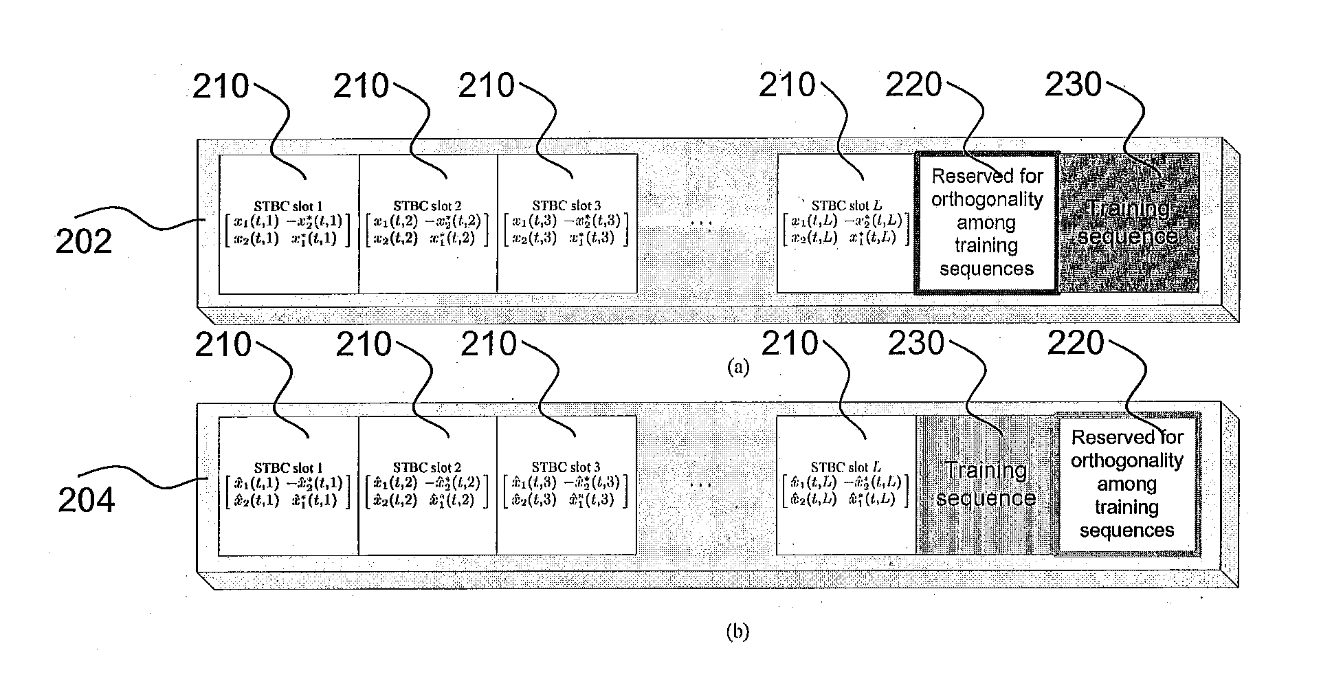
[0003]In general terms the invention relates to double space-time transmit diversity two path relay systems. The invention may also relate to phase rotation processing at the relay nodes, link selection based on signal to noise ratio (SNR), frame structure including training sequence, transmit- and receive-modes of two relays and / or cell planning strategies. This may have the advantage of reduced co-channel interference (CCI) between the relay nodes, reduced inter cell interference (ICI), reduced bit error rate and / or reduced quantity of feedback information.
[0031]using a minimal about of feedback information to bring about an improved system performance;
[0035]reducing or eliminating the noise collected at, the relays that is forwarded on to the destination when compared to prior art systems, e.g. systems using amplify-and-forward relaying.

Problems solved by technology

In point-to-point (PtoP) communications, there is a restriction on the transmit power of the transmitter due to the cost and complexity of radio frequency (RF) chain including many amplifiers, filters, and digital-to-analogue converters.
However, the relaying protocols mentioned suffer from spectral efficiency loss due to the two channel uses required for the transmission and reception at the relay nodes.

Method used


Image

  • Method of communication
  • Method of communication
  • Method of communication

Examples


Embodiment Construction

[0054]The following notations may be used in this specification. For a vector or matrix, the superscripts ‘T’ and ‘*’ respectively denote a transposition and a complex conjugate transposition. For a scalar w, the notation |w| denotes the absolute value of w. For a matrix W, the notation ∥W∥F denotes the Frobenius-norm of W. 0w denotes a w-by-w zero matrix and Iw denotes a w-by-w identity matrix. The notation W1 denotes a matrix inversion of the matrix W. [W]l,l denotes the lth diagonal element of W. E[•] denotes the expectation of a random variable.

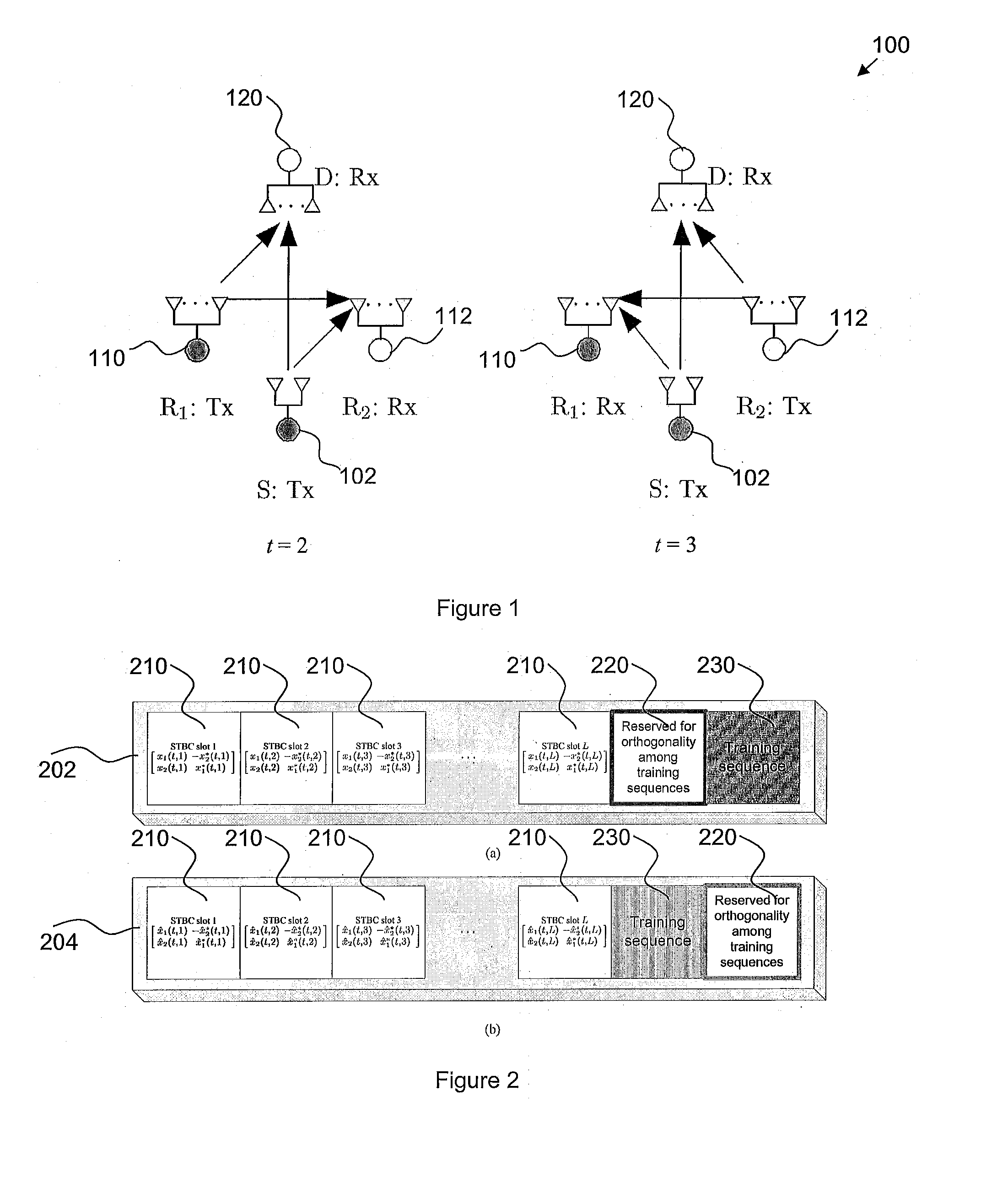
[0055]FIG. 1 shows a method 100 of transmission according to the example embodiment. The transmission uses two-path double space-time transmit diversity (DSTTD) and takes place from a source S 102 to a destination D 120 via relay stations R1110 and R2112. The relay stations R1110 and R2112 may relay in a decode-and-forward (DF) manner. In contrast with systems using other forms of relay, e.g. the amplify-and-forward relaying, the usage of...


PUM


Abstract

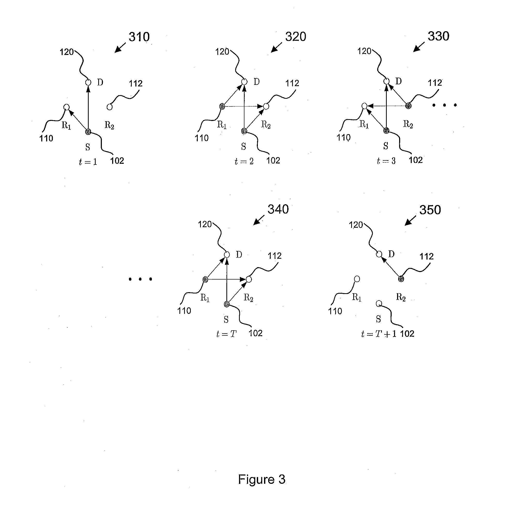
A method of communication comprising: at time=t: a first multiple antenna relay node decoding and forwarding a first STBC coded signal from a source node, and a first decoded and forwarded STBC signal from a second multiple antenna relay node, and a destination DSTTD receiver decoding the first STBC coded signal from the source node, and the first decoded and forwarded STBC signal from the second multiple antenna relay node; at time=t+1: the second multiple antenna relay node receiving a second STBC coded signal from the source node, and a second decoded and forwarded signal from the first multiple antenna relay node, and the destination DSTTD receiver decoding the second STBC coded signal from the source node, and the second decoded and forwarded signal from the first multiple antenna relay node.

Description

FIELD OF THE INVENTION[0001]The present invention relates to a method of communication.BACKGROUND[0002]In point-to-point (PtoP) communications, there is a restriction on the transmit power of the transmitter due to the cost and complexity of radio frequency (RF) chain including many amplifiers, filters, and digital-to-analogue converters. To enhance the communication performance under these circumstances, multiple transmitters cooperating with low power have been considered as candidates for future communications. Examples of such cooperative communication protocols with relays are physical layer network coding, analogue network coding, and various hybrid methods. However, the relaying protocols mentioned suffer from spectral efficiency loss due to the two channel uses required for the transmission and reception at the relay nodes. In other words, since a half-duplex (HD) relay cannot simultaneously receive and transmit signals, additional time, frequency, and / or code resources are ...

Claims


Application Information

Patent Timeline
IPC IPC(8): H04J11/00H04B7/14
CPCH04B7/0669H04B7/0673H04B7/2606H04B7/2656H04L1/0668H04L1/0643H04L2001/0097H04W40/06H04L1/0077
Inventor JOUNG, JIN GONSUN, SUMEI
Owner AGENCY FOR SCI TECH & RES
Learn More