Stator Manufacturing Method and Whirling Cutter Device

Inactive Publication Date: 2012-11-22
NAT OILWELL VARCO LP
View PDF11 Cites 10 Cited by
  • Summary
  • Abstract
  • Description
  • Claims
  • Application Information

AI Technical Summary

Benefits of technology

[0048]Offsetting the drive member in the way described above reduces the requisite angle of deflection of the universal joints and/or the length of the displacement member. Reduci

Problems solved by technology

Using a circular cutter tangentially to such lines inevitably will leave ridges, unless the cutter is also moved alo

Method used


Image

  • Stator Manufacturing Method and Whirling Cutter Device
  • Stator Manufacturing Method and Whirling Cutter Device
  • Stator Manufacturing Method and Whirling Cutter Device

Examples


Embodiment Construction

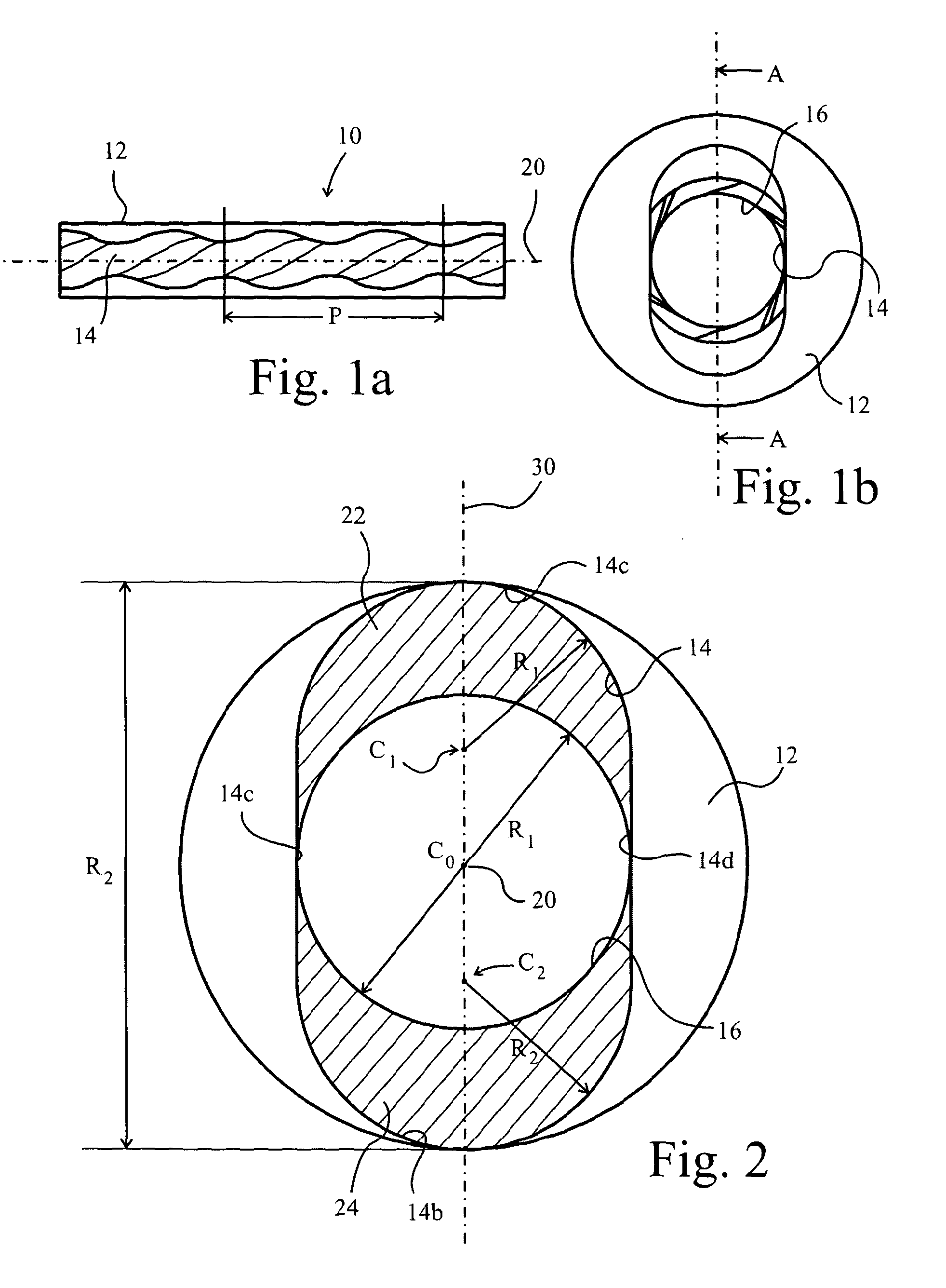
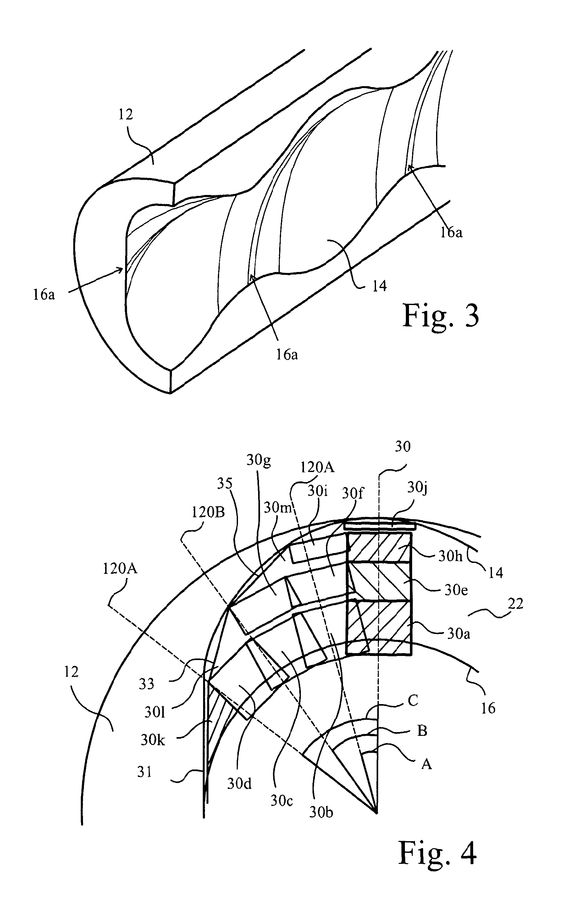
[0069]In the drawings, a stator 10 comprises a body 12 in the form of a tube having a bore 14. The bore 14 is a double helix whose profile at any position along a longitudinal axis 20, which is central to the bore 14 is an oval shape that is swept by a circle of radius R1 translating from centre C0 coincident with the longitudinal axis 20 to two further centres C1, C2. The distance C1, or C2, to C0, is the eccentricity of the stator. Thus, starting with a tube having a central circular bore 16 of diameter R1, at any axial position along the axis 20, C shaped segments 22,24 (hatched areas in FIG. 2) must be removed. However, the radial axis 30 of the bore 14 rotates as the profile progresses along the stator 10 so that, when viewed from one end as shown in FIG. 1b, there is only a circular bore visible, equal to the original bore 16 of the body 12. However, as mentioned above, the bore 14 is not circular but a double helix of pitch P, as shown in FIG. 1a. The diameter R1 is referred ...


PUM

PropertyMeasurementUnit
Diameteraaaaaaaaaa
Torqueaaaaaaaaaa
Displacementaaaaaaaaaa

Abstract

A method for machining a helical bore of a stator comprises providing a stator body with a bore. In addition, the method comprises providing a first and a second machining device. The first machining device comprises a milling head coupled to the end of a shaft and a rotary cutter mounted to the milling head for rotation about an axis transverse to the longitudinal axis. The second machining device comprises a whirling head on the end of a shaft and a whirling cutter mounted to the whirling head for rotation about an axis parallel to the longitudinal axis but offset therefrom by a selectively variable degree. Further, the method comprises driving the first machining device through the bore multiple times with the rotary cutter following a helical path. Still further, the method comprises driving the second machining device through the bore with the whirling cutter following the same helical path.

Description

CROSS REFERENCE TO RELATED APPLICATIONS[0001]This application is a 35 U.S.C. §371 national stage application of PCT / GB2011 / 050200 filed Feb. 4, 2011, which claims the benefit of British Patent Application No. 1001836.4 filed Feb. 4, 2010, both of which are incorporated herein by reference in their entireties for all purposes.STATEMENT REGARDING FEDERALLY SPONSORED RESEARCH OR DEVELOPMENT[0002]Not applicable.BACKGROUND[0003]1. Field of the Invention[0004]This invention relates to a method of machining the stators of progressive cavity pumps. However, the stator of such pumps corresponds with the stators of progressive cavity motors and therefore the invention is also applicable to such stators. The present invention finds particular application in the small size range.[0005]2. Background of the Technology[0006]Stators of such machines are frequently moulded from rubber or like elastomer, where a core of the mould is unscrewed from the stator bore after moulding. This is perfectly sat...

Claims


Application Information

Patent Timeline
IPC IPC(8): B23C3/32B23P15/00B23C9/00
CPCB23C3/32B23C9/005Y10T409/303808Y10T409/304424B23Q5/046Y10T409/303752
Inventor WILMOT, WESSLEY
Owner NAT OILWELL VARCO LP
Why Eureka
Try Eureka