

Automotive power supply system designed to ensure stability in charging storage batteries
- Summary
- Abstract
- Description
- Claims
- Application Information
AI Technical Summary
Benefits of technology
Problems solved by technology
Method used
Image

Examples
first embodiment
[0037] Referring to the drawings, wherein like reference numbers refer to like parts in several views, particularly to FIGS. 1 to 3, there is shown an automotive power supply system according to the invention.
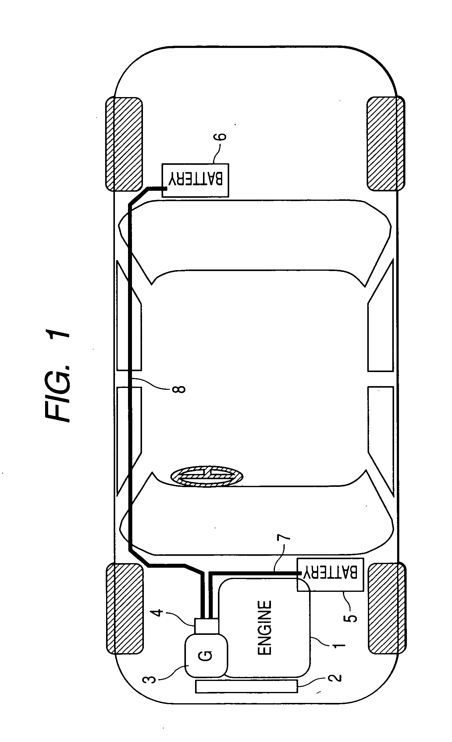
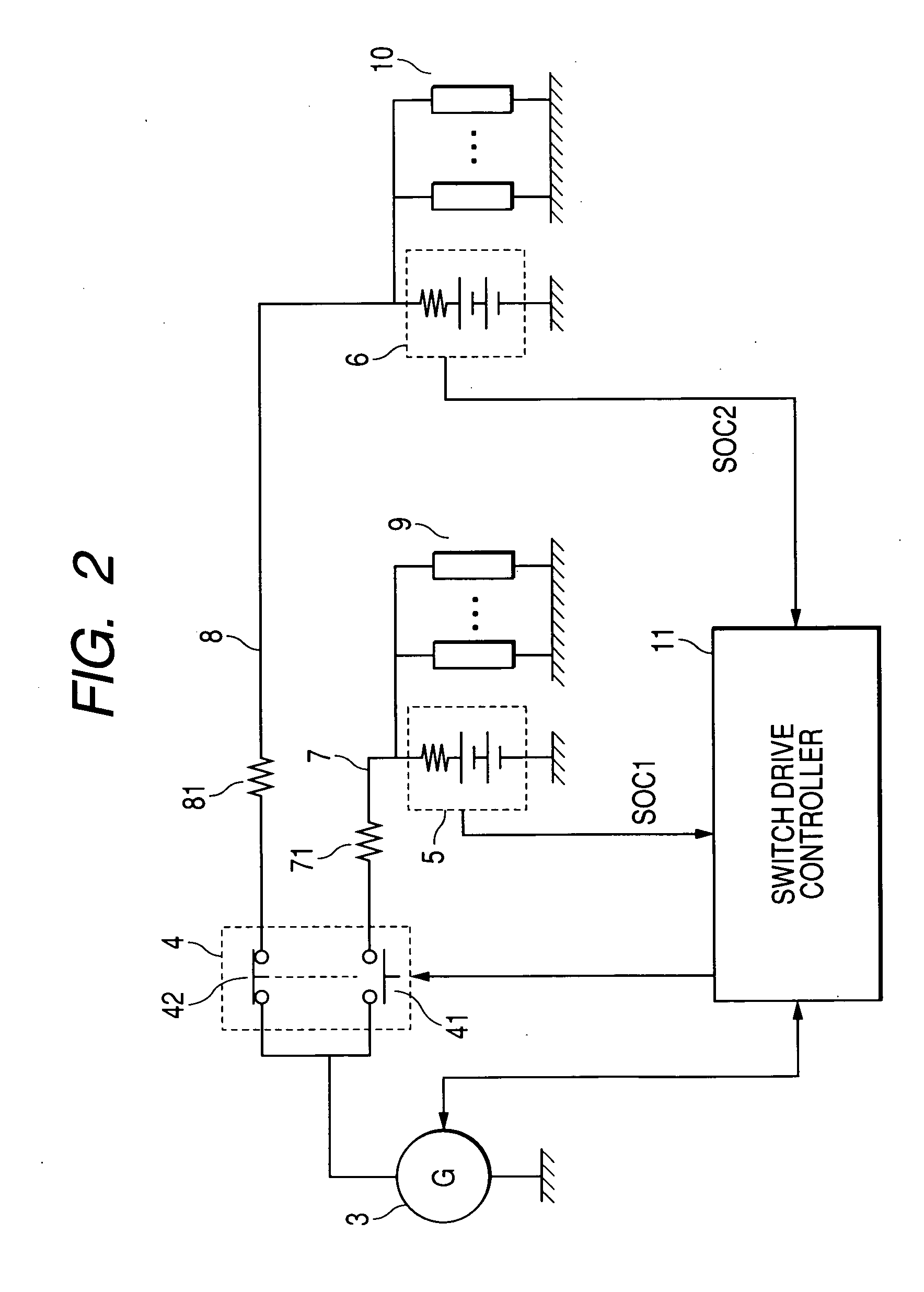
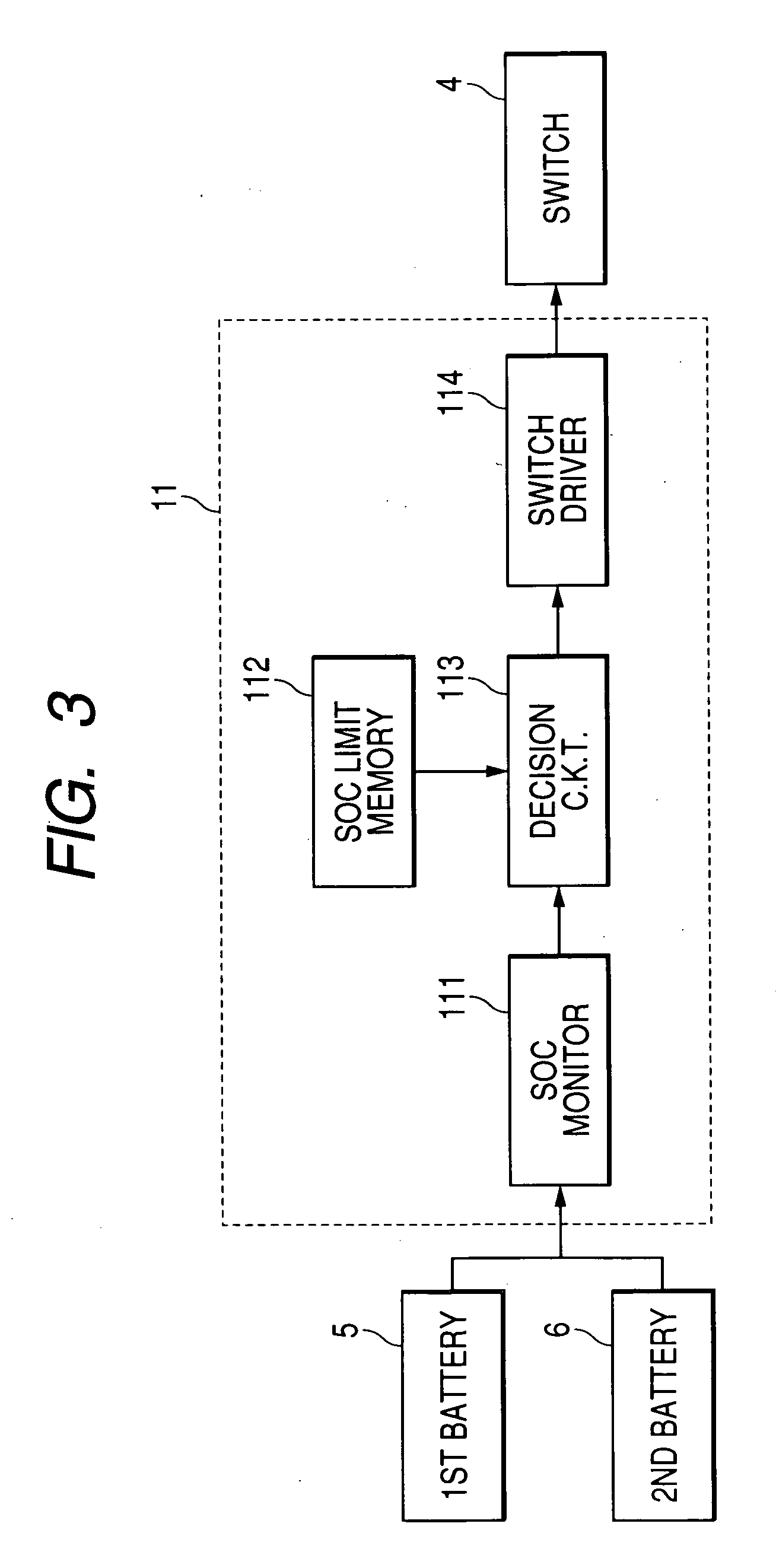
[0038] The automotive power supply system, as can be seen from FIG. 1, consists of an automotive internal combustion engine 1, a drive belt 2, an electric generator 3, a switching device 4, a first storage battery 5, a second storage battery 6, a first power supply cable 7, a second power supply cable 8, and a switch drive controller 11, as illustrated in FIG. 2.
[0039] The engine 1 is started upon actuation of an engine starter (not shown) and produces torque to drive the vehicle. The torque is also used to rotate the generator 3 through the belt 2 to produce electric power.
[0040] The switching device 4 works to selectively establish one of electric communications between the generator 3 and the first battery 5 and between the generator 3 and the second battery 6. Specificall...
second embodiment
[0056]FIG. 5 shows a switch drive controller 11 of the automotive power supply system according to the invention.
[0057] The automotive power supply system of this embodiment includes a speed sensor 30 and a throttle position sensor 40. The speed sensor 30 works to measure the speed of the vehicle equipped with the automotive power supply system and output a signal indicative thereof to the switch drive controller 11. The throttle position sensor 40 works to measure the degree of opening, i.e., a valve position of a throttle valve (not shown) of the engine 1 and output a signal indicative thereof to the switch drive controller 11.
[0058] The switch drive controller 11 consists of a deceleration monitor 121, a switch drive signal generator 122, a switch driver 123, and an electric generation controller 124. Other arrangements of the automotive power supply system are identical with those in the first embodiment, and explanation thereof in detail will be omitted here.
[0059] The decele...
third embodiment
[0077] As apparent form the above discussion, the switch drive controller 11 of the third embodiment works to maintain the first and second batteries 5 and 6 within a serviceable capacity range intermediate between an overcharged capacity and an undercharged capacity. The switch drive controller 11, as described above, prolongs the connection duration of each of the switches 41 and 42 when the power consumption of a corresponding one of the batteries 5 and 6 increases, thus avoiding rapid voltage drops of the batteries 5 and 6.
PUM
 Abstract
Description
Claims
Application Information