Low Profile Male Connector

Inactive Publication Date: 2012-11-22
APPLE INC
View PDF5 Cites 5 Cited by
  • Summary
  • Abstract
  • Description
  • Claims
  • Application Information

AI Technical Summary

Benefits of technology

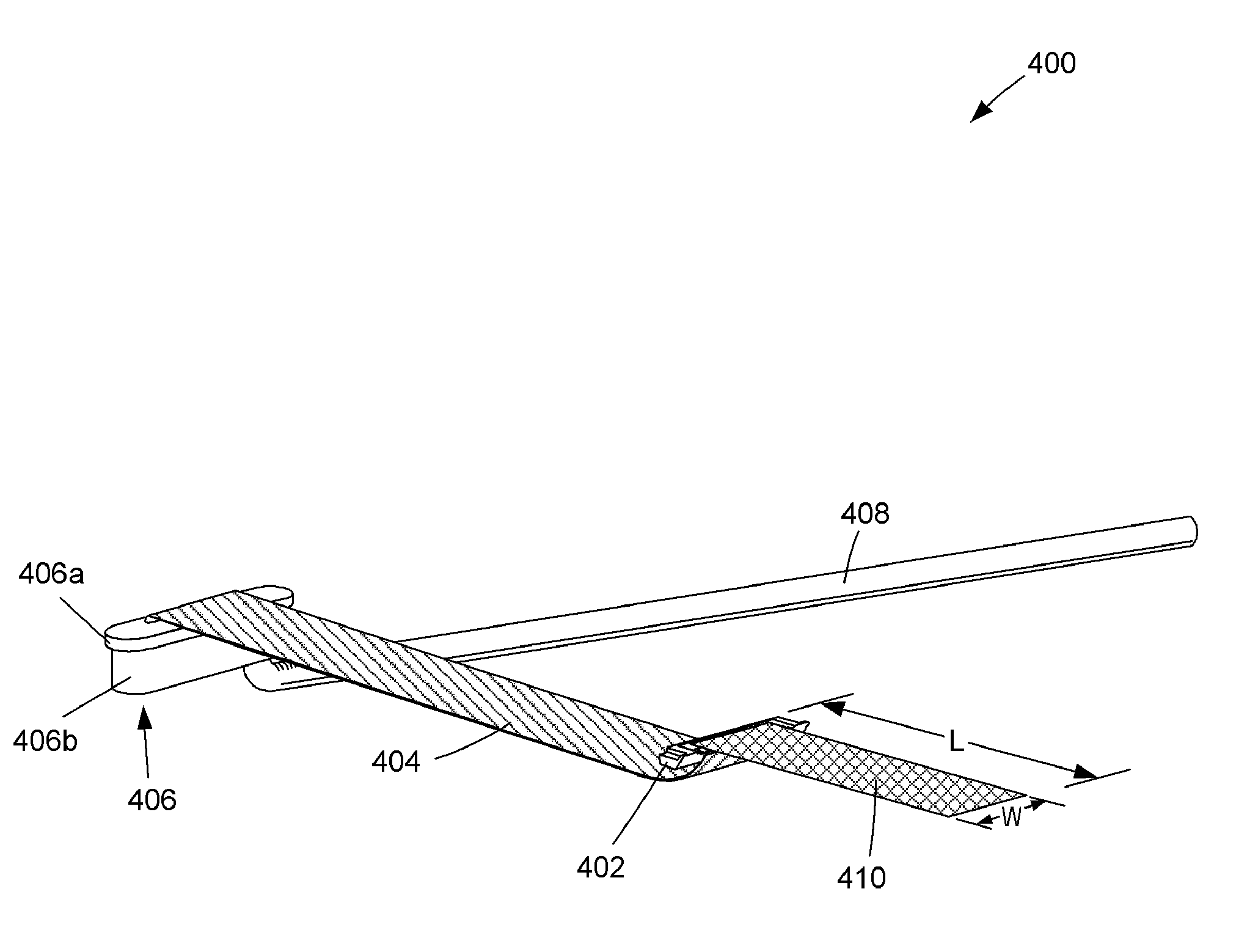
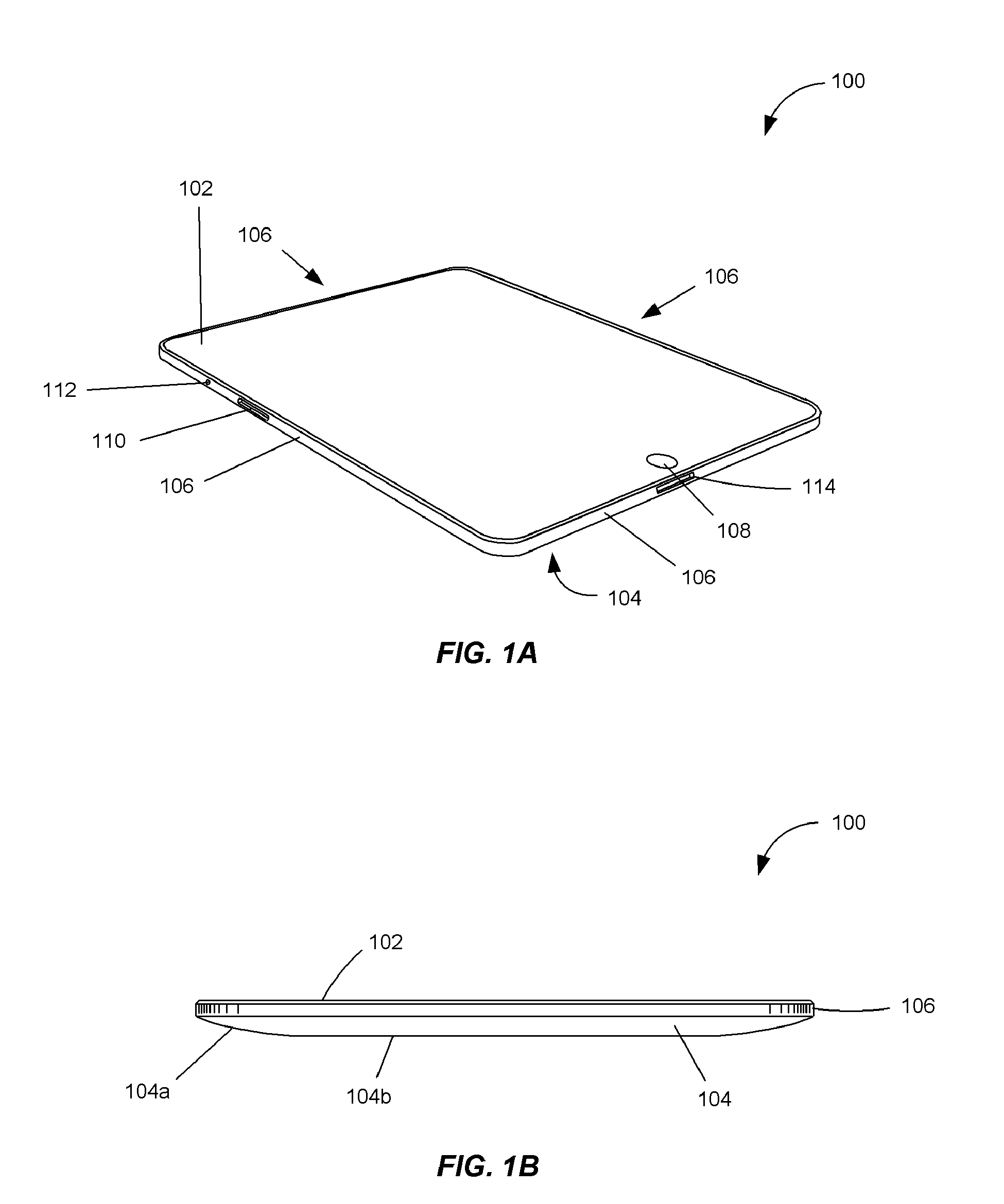
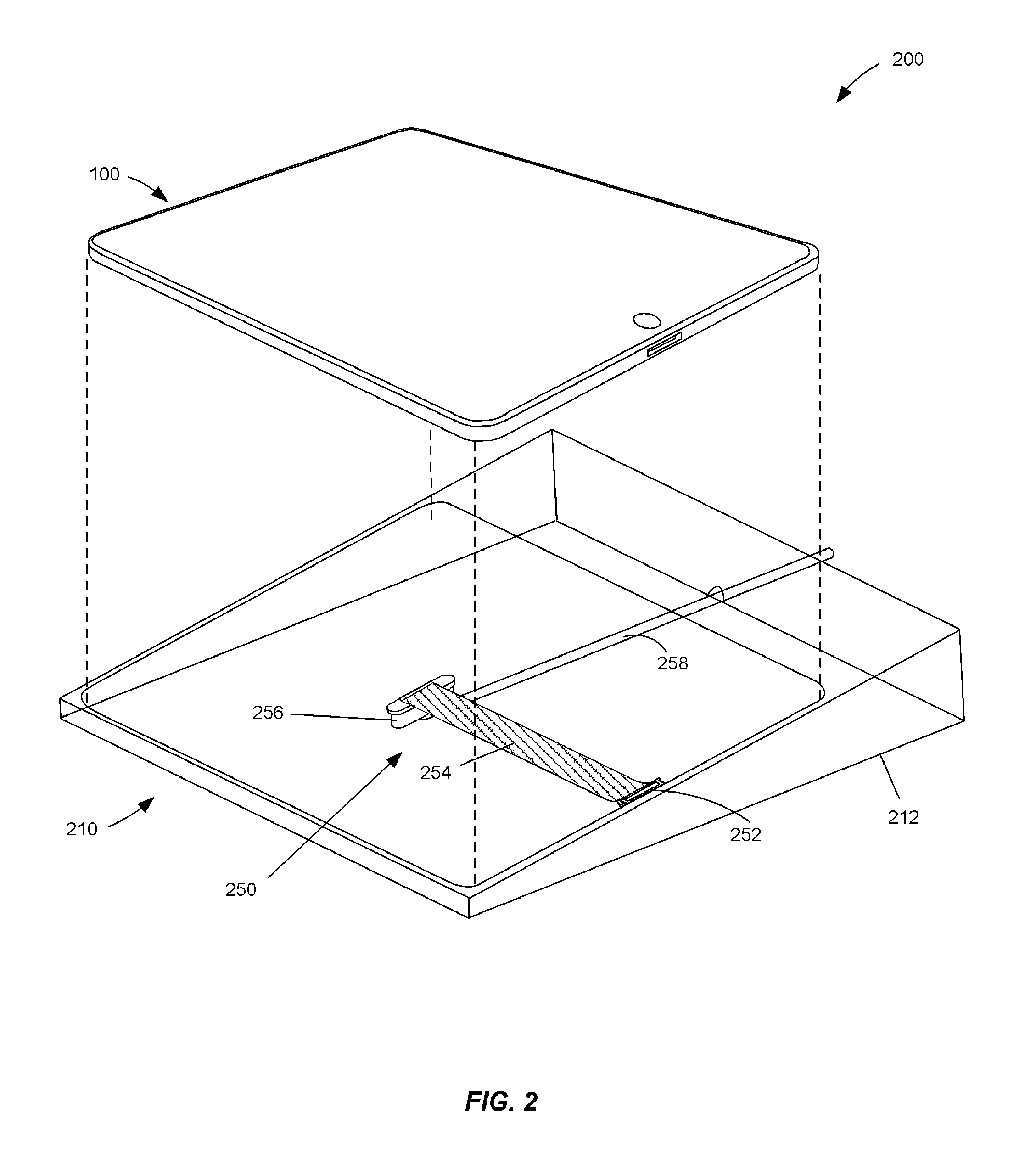
[0009]For example, the plug housing may include a rear surface that is at least one of curved and angled with respect to a front surface of the plug housing so as to match a contour of an outer surface of an electronic device. In this fashion, a size and visual protrusion of the plug housing may advantageously be minimized. For another example, the plug housing may have a depth and an interior cavity designed to accommodate a number of pins. The pins may each include a connecting portion, and the connecting portions of adjacent pairs of pins may be staggered with respect to one another. In this fashion, an interference between adjacent pins may be advantageously reduced. For yet another example, the connecting portions of pins may extend substantially perpendicular to a rear surface of the plug housing. In this fashion, the integrity of the pins and the integrity of a coupling between the pins and the cable may advantageously be increased.
[0011]For example, the pin may include a base, an elongated shaft, and an engaging portion. The base may include a cutout for extending a length of the elongated shaft. In this fashion, forces applied to and stresses within the pin may advantageously be reduced. For another example, the elongated shaft may include a limit stop protruding from a top surface of the elongated shaft. The limit stop may distribute a force applied to the elongated shaft upon engagement of the engaging portion with the receiving pin. In this fashion, forces applied to and stresses within the pin may advantageously be reduced.

Problems solved by technology

However, as the size of electrical connectors is reduced, numerous problems arise.
Reducing the size of the electrodes tends to increase stresses of and forces applied to the electrode upon engagement with a receiving connector.
As a result, the integrity and effectiveness of the connector is reduced over time.
Such cable assemblies and electrical connectors often protrude and extend from electronic devices in a disorganized manner.
As a result, the electrical connectors and cable assemblies attached thereto are often distracting and unsightly.

Method used


Image

  • Low Profile Male Connector
  • Low Profile Male Connector
  • Low Profile Male Connector

Examples


first embodiment

[0111]FIG. 7A is a side view of a pin 700 according to the present invention. Pin 700 may be made using any type of rigid conductive material. For example, pin 700 may be made using one or more metals such as copper, nickel, tin or magnesium. Pin 700 includes a base 702 for supporting pin 700 within a plug housing, an elongated shaft 704 extending from base 702, and an engaging portion 706 located on an end of elongated shaft 704 opposite base 702 for engaging a receiving pin of a corresponding receptacle connector. Base 702 includes a connecting portion 708.

[0112]According to one embodiment, as illustrated in FIG. 7A, connecting portion 708 extends from an upper edge of pin 700. Connecting portion 708 may extend from the upper edge at any one of a variety of angles. For example, connecting portion 708 may extend at an angle of approximately 45 degrees from a direction in which elongated shaft 704 extends from base 702. For another example, connecting portion 708 may extend at an an...

second embodiment

[0113]FIG. 7B is a side view of a pin 700 according to the present invention. According to one embodiment, as illustrated in FIG. 7B, connecting portion 708 extends from a lower edge of pin 700. Connecting portion 708 may extend from the lower edge at any one of a variety of angles. For example, connecting portion 708 may extend at an angle of approximately 45 degrees from a direction in which elongated shaft 704 extends from base 702. For another example, connecting portion 708 may extend at an angle in a range of approximately 30 to 60 degrees from a direction in which elongated shaft 704 extends from base 702. For yet another example, connecting portion 708 may extend at an angle of less than 30 degrees or greater than 60 degrees from a direction in which elongated shaft 704 extends from base 702. In one embodiment, as illustrated in FIG. 7B, connecting portion 708 extends in a direction away from a top surface of base 702. In another embodiment, connecting portion 708 extends in...


PUM


Abstract

Various embodiments of low profile male connectors are described. In one embodiment, a connector includes a plug housing having a depth and an interior cavity designed to accommodate pins that extend within the interior cavity in a direction of the depth. The plug housing may be designed to be fully insertable into a receptacle connector of an electronic device, and to have a rear surface that conforms with a shape of an exterior surface of the electronic device. The pins arranged in the plug housing may include various features, such as connecting portions protruding from the plug housing at an angle of approximately 90 degrees for coupling to a cable, bases including cutouts for extending a length of an elongated shaft of the pin, barbs for engaging the plug housing, and limit stops for distributing a force applied to the elongated shaft upon engagement with a receiving pin.

Description

BACKGROUND[0001]1. Field of the Invention[0002]The present invention relates to a connector. More particularly, the present invention relates to a low profile male connector adapted to be fully insertable into an electronic device and contoured to match an outer surface of the electronic device.[0003]2. Description of the Related Art[0004]Numerous types of electrical connectors for interconnecting electronic devices exist in the art. Such connectors typically include a receptacle (female) connector and a plug (male) connector. The plug connector may engage the receptacle connector for establishing an electrical connection between pin-shaped electrodes arranged in each connector.[0005]With the diminishing size of electronic devices, there is a significant desire to similarly reduce the size of electrical connectors. However, as the size of electrical connectors is reduced, numerous problems arise. For example, reductions in a size of an electrical connector requires a corresponding r...

Claims


Application Information

Patent Timeline
IPC IPC(8): H01R24/00H01R13/02
CPCH01R12/592H01R12/65H01R13/516G06F1/1632H01R13/46H01R31/06H01R13/26H01R13/633H01R27/02
Inventor VILLARREAL, CESAR LOZANODOLCI, DOMINIC E.SPIELMANN, VICTORIA A.MARIANO, RICARDO A.KWAN, ALEXANDER M.SMEENGE, JAMES G.DE LULIIS, DANIELE G.
Owner APPLE INC
Why Eureka
Try Eureka