Thermoelectric unit

a technology of thermoelectric units and electric connectors, which is applied in the direction of thermoelectric devices with peltier/seeback effect, thermoelectric device details, electric apparatus, etc., can solve the problems of less efficiency, less effectiveness, and conventional tegs according to the prior art are not optimally suitable for use, and achieve simple and cost-effective production, easy placement and attachment, and facilitate the effect of attachment and removal of electric connectors

Inactive Publication Date: 2012-11-29
BEHR GMBH & CO KG
View PDF7 Cites 10 Cited by
  • Summary
  • Abstract
  • Description
  • Claims
  • Application Information

AI Technical Summary

Benefits of technology

[0015]According to a further embodiment, the electrical connector can be embodied as a one-part multiple connector clamp, which laterally spans the inner flat tube of the double-walled cooling tube and the inner flat tube of the at least one further double-walled cooling tube on one lateral surface, wherein the multiple connector clamp is embodied in order to connect two thermoelectric modules assigned to the double-walled cooling tube to at least one thermoelectric module of a further double-walled cooling tube. In this embodiment the electrical connector can also be produced simply and cost-effectively and is easy to place and to attach, in particular when it is necessary to connect the thermoelectric modules of several cooling tubes.
[0016]The electrical connector can also be embodied as a multipart clamp, of which a first part spans a lateral surface of the inner flat tube of the double-walled cooling tube and at least one second part spans the inner flat tube of a further double-walled cooling tube on a lateral surface, wherein the first part and the second part can be connected positively in order to connect in an electrically conducting manner at least one thermoelectric module assigned to the double-walled cooling tube to at least one thermoelectric element assigned to the further double-walled cooling tube. For example, the one part and the at least one further part can be embodied as hooks that can engage in one another. This embodiment provides the advantage that, due to the separate steps of the positioning and connecting of the at least two parts of the clamp, an attachment and removal of the electric connector can be facilitated.
[0017]According to a further embodiment, the electrical connector can be spanned by a narrow side of the inner tube and have a bushing in the region of a subsidiary surface of the inner tube connecting the main surfaces of the inner tube, which bushing can be embodied to be connected to an insert conductor in an electrically conducting manner. The insert conductor can be, e.g., an electrically insulated copper cable or a conductor clamp, with which individual TEM tubes can be connected or a connection can be produced to an external power supply. This makes it possible to quickly contact the individual thermoelectric modules even over several cooling tubes.
[0018]The outer flat tube of the double-walled cooling tube can also have a first opening and, on a main surface of the outer flat tube of the further double-walled cooling tube, have a second opening, which is arranged at a position lying opposite the first opening and wherein the electrical connector is embodied as a pin plug, which is guided through the first opening and the second opening. By means of such openings in connection with pin plugs, there is a particularly space-saving possibility of connecting thermoelectric modules in an electrically conducting manner.
[0019]According to an embodiment, the pin plug can have a non-conducting sheath. The plug connector can be embodied as a double plug or a conductor pin with an electrically conducting core and an electrically insulated sheath, so that an improved electrical insulation of the contact between the thermoelectric modules and an environment is ensured. Particularly with adverse environmental conditions of the thermoelectric unit, such as in vehicle use, this will lead to an increased service life of the same.

Problems solved by technology

Conventional TEMs according to the prior art are not optimally suitable for use in a TEG due to their design and joining technique and also are less effective.
Conventional TEGs are less efficient due to the increased heat transmission resistance between thermoelectrically active materials and a heat source / heat sink.
An integration of the TEM into a heat exchanger has also proven to be impractical.
Furthermore, on the gas-side contact of the TEM in the heat exchanger there is often only a low heat transfer.
According to the prior art, accordingly conventional TEMs are not optimally suitable for use in a TEG due to their design and joining technique and are less effective.
The electrical connection is often complex and unstable.

Method used


Image

  • Thermoelectric unit
  • Thermoelectric unit
  • Thermoelectric unit

Examples


Embodiment Construction

[0060]In the following description of favorable exemplary embodiments of the present invention the same or similar reference characters are used for the elements shown in the various drawings with similar action, a repeated description of these elements being omitted.

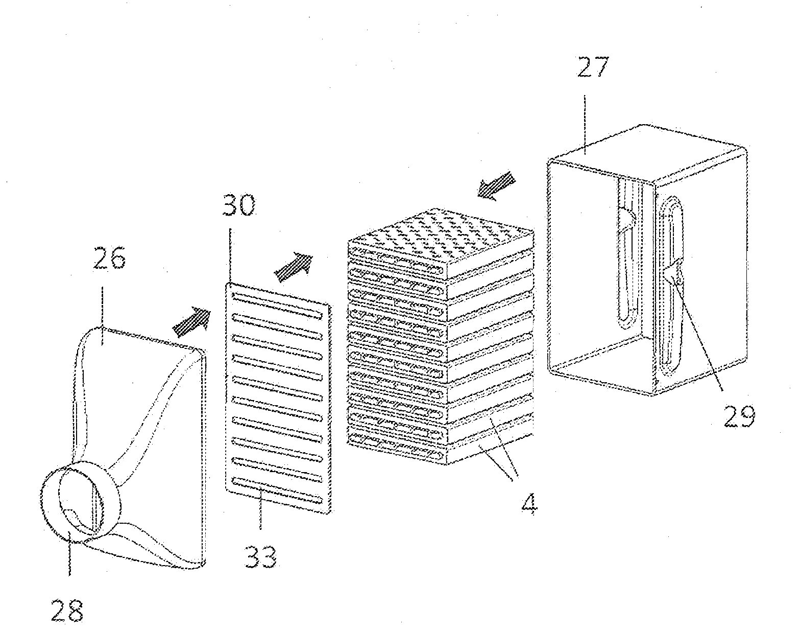
[0061]A TEM tube according to the exemplary embodiments of the invention presented here is formed by a two-walled rectangular tube, wherein TE-active materials are introduced into an intermediate space of the two walls. An inner tube of the TEM tube is in contact with one of two fluids flowing through a TEG, an outer tube of the TEM tube is in contact with the other of the two fluids flowing through the TEG.

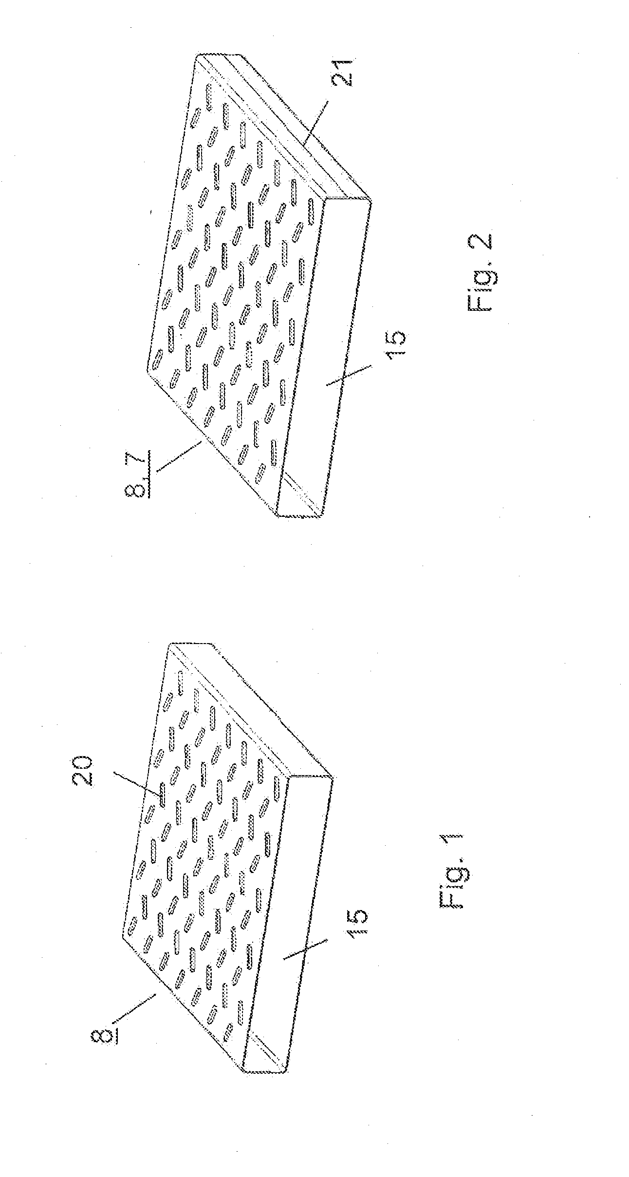
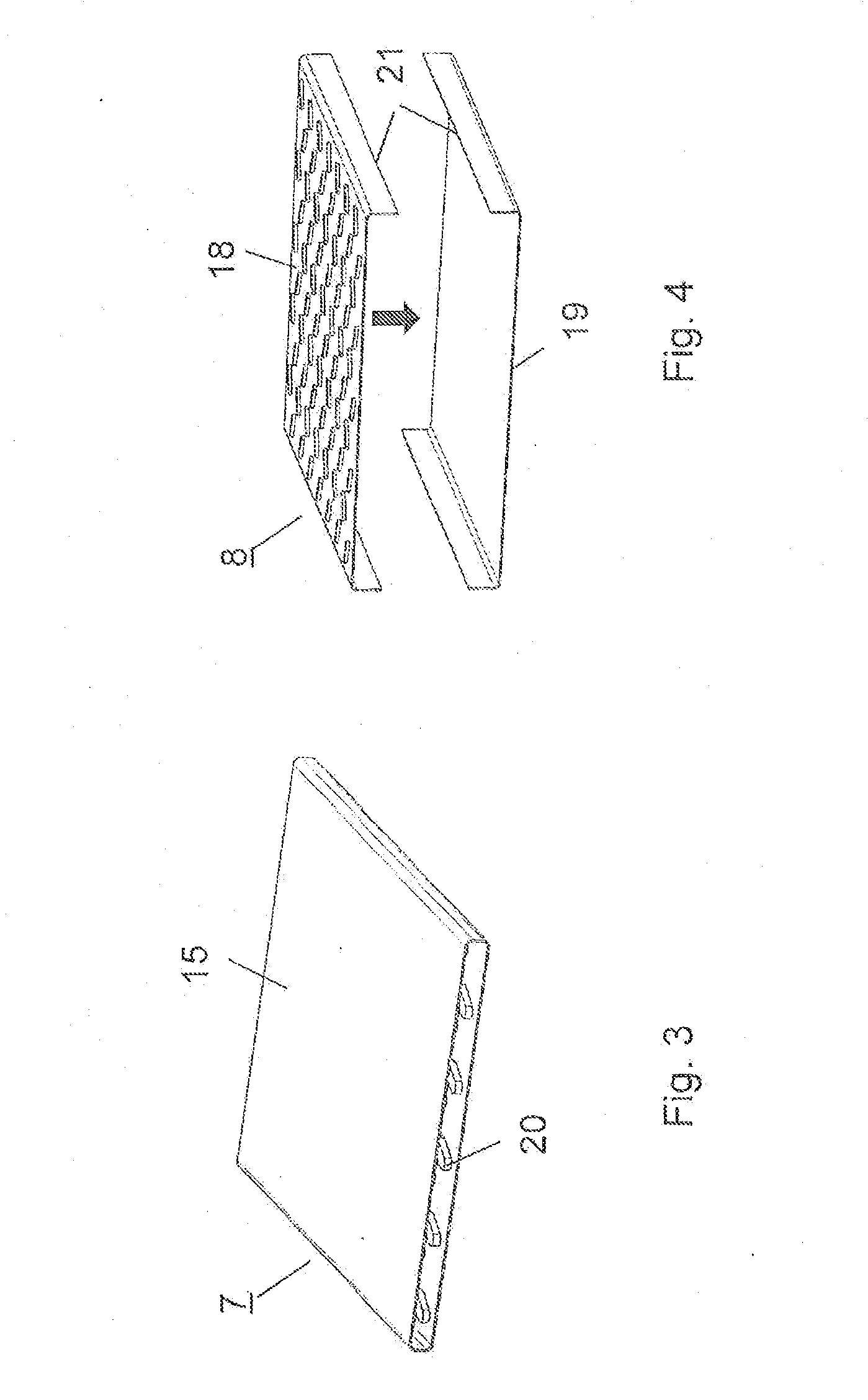
[0062]Various exemplary embodiments for inner and / or outer tubes of the two-walled rectangular tube are shown in FIGS. 1 through 9.

[0063]Thus FIG. 1 shows in an isometric image a one-part outer tube or outer flat tube 8 for use in a TEG. The outer flat tube 8 has a nonconductor 15 in an interior. A main surface direc...


PUM


Abstract

A thermoelectric unit for electrically interconnecting a plurality of thermoelectric modules. The thermoelectric unit includes a first thermoelectric module having a plurality of interconnected thermoelectric elements, the first thermoelectric module being interposed between a main surface of an inner flat tube and a main surface of an outer flat tube of a double-walled cooling tube, a second thermoelectric module being interposed between a second main surface of the inner flat tube and a second main surface of the outer flat tube of the double-walled cooling tube and/or between a main surface of an inner flat tube and a main surface of an outer flat tube of a second double-walled cooling tube, and an electrical connector designed to connect the first thermoelectric module to the second thermoelectric module in an electrically conducting manner.

Description

[0001]This nonprovisional application is a continuation of International Application No. PCT / EP2010 / 069784, which was filed on Dec. 15, 2010, and which claims priority to German Patent Application No. DE 10 2009 058 674.1, which was filed in Germany on Dec. 16, 2009, and which are both herein incorporated by reference.BACKGROUND OF THE INVENTION[0002]1. Field of the Invention[0003]The present invention relates to a thermoelectric unit[0004]2. Description of the Background Art[0005]The energy stored in exhaust gas in the form of heat has hitherto been discharged into the environment unused. In order to increase the effectiveness of a system, e.g., a vehicle, and consequently to reduce the discharge of CO2 in operation, a thermoelectric generator (TEG) can be implemented, the thermoelectric module (TEM) of which converts part of the heat into electric energy and feeds it back into the system. The TEG can be accommodated with different use at any point in the exhaust gas system or in t...

Claims


Application Information

Patent Timeline
Patent Type & Authority Applications(United States)
IPC IPC(8): H01L35/32
CPCH01L35/30H01L35/10H10N10/82H10N10/13
Inventor BREHM, HOLGERHIMMER, THOMASHECKENBERGER, THOMASRIEDEL, RUDOLF
Owner BEHR GMBH & CO KG
Why Eureka
Try Eureka