Laser processing apparatus

a technology of laser processing and laser beam, which is applied in the direction of metal working apparatus, manufacturing tools, welding/soldering/cutting articles, etc., can solve the problems of difficult to reliably determine the spectrum caused by plasma and inherent in materials, and achieve the effect of reliably detecting the plasma light generated

Inactive Publication Date: 2012-11-29
DISCO CORP
View PDF2 Cites 26 Cited by
  • Summary
  • Abstract
  • Description
  • Claims
  • Application Information

AI Technical Summary

Benefits of technology

[0012]As described above, the laser processing apparatus according to the present invention includes the reflecting means provided on the optical axis of the focusing means for allowing the pass of the laser beam oscillated by the laser beam oscillating means and reflecting the plasma light generated from the workpiece, the wavelength detecting means for detecting the wavelength of the plasma light reflected by the reflecting means, and the control means for determining the material of the workpiece according to a detection signal from the wavelength detecting means to control the laser beam applying means. For example, in applying a laser beam to a substrate of a wafer having a plurality of bonding pads formed on the front side from the back side of the substrate to form a plurality of laser processed holes respectively reaching the bonding pads, it is possible to detect that the laser processed holes formed in the substrate have reached the bonding pads according to a spectral wavelength signal from the wavelength detecting means. Accordingly, when it is detected that each laser processed hole has reached the corresponding bonding pad, the application of the laser beam to the wafer can be stopped to thereby prevent the bonding pad from melting to be perforated. Further, the reflecting means is located on the optical axis of the focusing means and the plasma light generated by applying the laser beam to the workpiece can be detected on the optical axis. Accordingly, it is possible to reliably detect the plasma light generated by applying the laser beam to a bonding pad of metal located at the bottom of a laser processed hole.

Problems solved by technology

Accordingly, even when a plasma is generated by the application of the laser beam, it is difficult to reliably determine the spectrum caused by the plasma and inherent in the material.

Method used


Image

  • Laser processing apparatus
  • Laser processing apparatus
  • Laser processing apparatus

Examples


Embodiment Construction

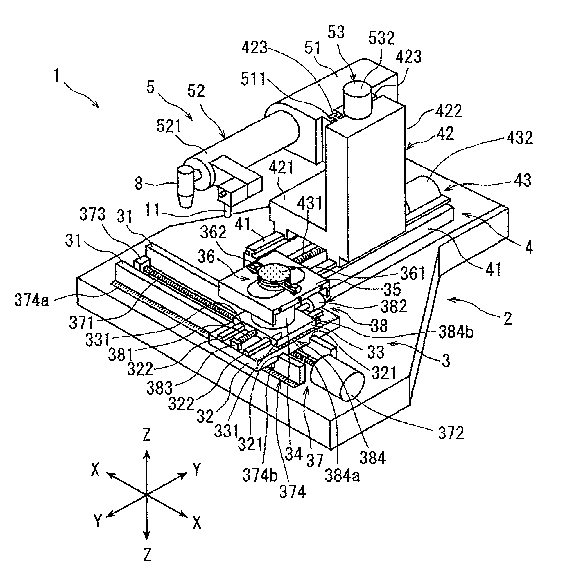
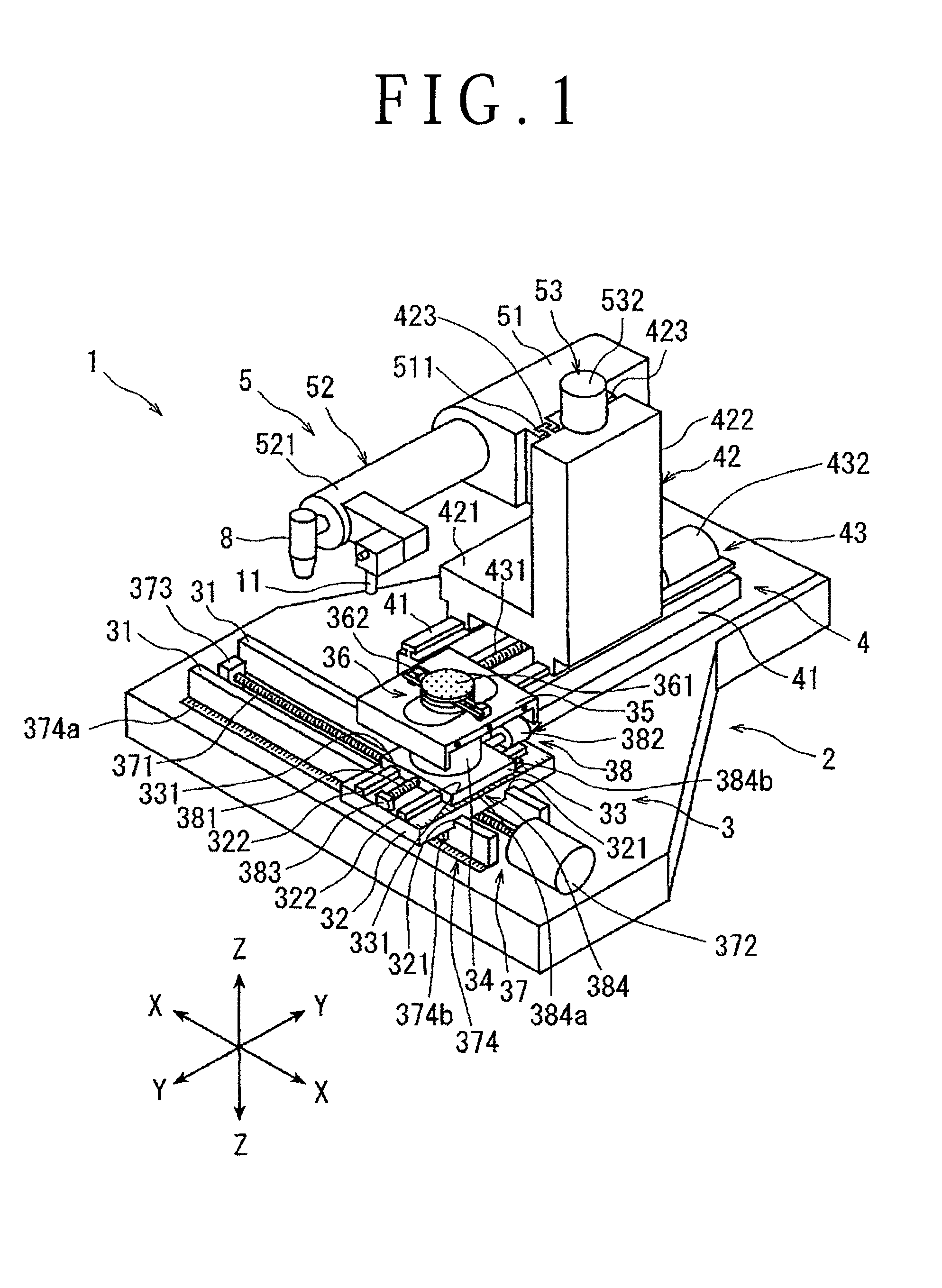
[0024]A preferred embodiment of the laser processing apparatus according to the present invention will now be described in detail with reference to the attached drawings. FIG. 1 is a perspective view of a laser processing apparatus 1 according to a preferred embodiment of the present invention. The laser processing apparatus 1 shown in FIG. 1 includes a stationary base 2, a chuck table mechanism 3 for holding a workpiece, the chuck table mechanism 3 being provided on the stationary base 2 so as to be movable in a feeding direction (X direction) shown by an arrow X, a laser beam applying unit supporting mechanism 4 provided on the stationary base 2 so as to be movable in an indexing direction (Y direction) shown by an arrow Y perpendicular to the X direction, and a laser beam applying unit 5 provided on the laser beam applying unit supporting mechanism 4 so as to be movable in a focal position adjusting direction (Z direction) shown by an arrow Z.

[0025]The chuck table mechanism 3 inc...


PUM

PropertyMeasurementUnit
diameteraaaaaaaaaa
spectral wavelengthaaaaaaaaaa

Abstract

A laser processing apparatus includes a chuck table for holding a workpiece and a laser beam applying unit for applying a laser beam to the workpiece. A laser beam oscillating unit oscillates a laser beam and a focusing unit focuses the laser beam onto the workpiece. A reflecting unit is provided on the optical axis of the focusing unit. A wavelength detecting unit detects the wavelength of the plasma light reflected by the reflecting unit, and a controller determines the material of the workpiece according to a detection signal from the wavelength detecting unit, to control the laser beam applying unit.

Description

BACKGROUND OF THE INVENTION[0001]1. Field of the Invention[0002]The present invention relates to a laser processing apparatus for forming a laser processed hole in a workpiece such as a semiconductor wafer.[0003]2. Description of the Related Art[0004]In a semiconductor device fabrication process, a plurality of crossing division lines called streets are formed on the front side of a substantially disk-shaped semiconductor wafer to thereby partition a plurality of regions where devices such as ICs and LSIs are respectively formed. The semiconductor wafer is cut along the streets to thereby divide the regions where the devices are formed from each other, thus obtaining individual semiconductor chips.[0005]For the purposes of achieving smaller sizes and higher functionality of equipment, a module structure having the following configuration is in practical use. This module structure is such that a plurality of devices are stacked and bonding pads provided on each device are connected t...

Claims


Application Information

Patent Timeline
Patent Type & Authority Applications(United States)
IPC IPC(8): B23K26/00
CPCB23K26/032B23K26/063B23K26/0643B23K2201/40B23K26/0876B23K26/381B23K26/4075B23K26/0861B23K26/0622B23K26/382B23K26/40B23K2101/40B23K2103/50
Inventor NOMARU, KEIJIMORIKAZU, HIROSHINISHINO, YOKO
Owner DISCO CORP
Why Eureka
Try Eureka