Power distribution system

a technology of power distribution system and power supply, applied in the direction of dc network circuit arrangement, ac-d ac network circuit arrangement, etc., can solve the problem of complicated construction of reverse power flow prevention device, and achieve the effect of lowering cos

Inactive Publication Date: 2012-11-29
PANASONIC CORP
View PDF3 Cites 23 Cited by
  • Summary
  • Abstract
  • Description
  • Claims
  • Application Information

AI Technical Summary

Benefits of technology

[0006]In view of the above insufficiency, the present invention has been aimed to propose a power distribution system which can be implemented at a lowered cost in comparison with a configuration where each distributed power source other than a solar cell is provided with a reverse power flow prevention device.
[0008]According to the above configuration, in contrast to a situation where each distributed power source other than the solar cell is provided with a reverse current flow prevention device, whereby the power distribution system can be implemented at a lowered cost.

Problems solved by technology

In such a power distribution system, during the daytime, the solar cell can generate sufficient power, and therefore generated power of the solar cell is likely to exceed consumed power and cause an excess (hereinafter referred to as “excess power”) of power.
The reverse power flow prevention device has a complicated construction for protection of the commercial power system.

Method used


Image

  • Power distribution system
  • Power distribution system
  • Power distribution system

Examples


first embodiment

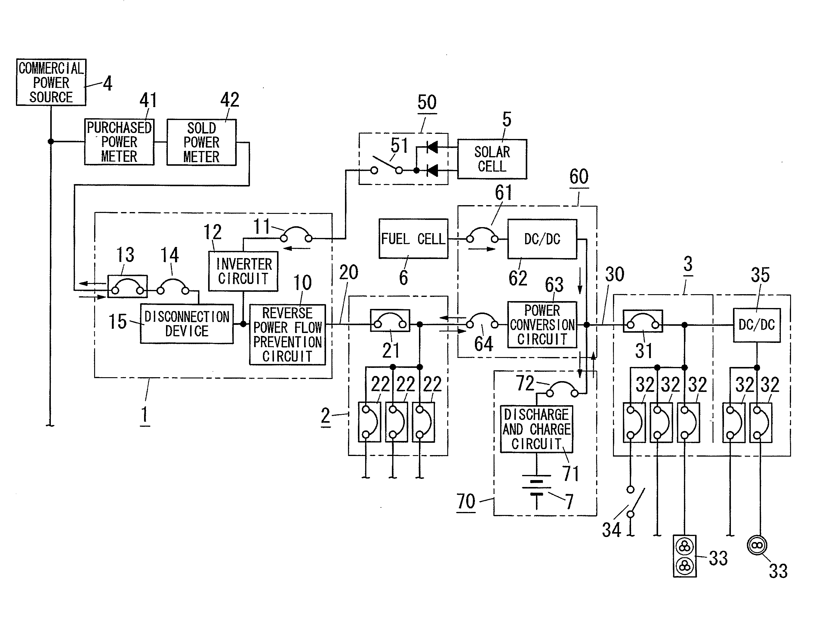
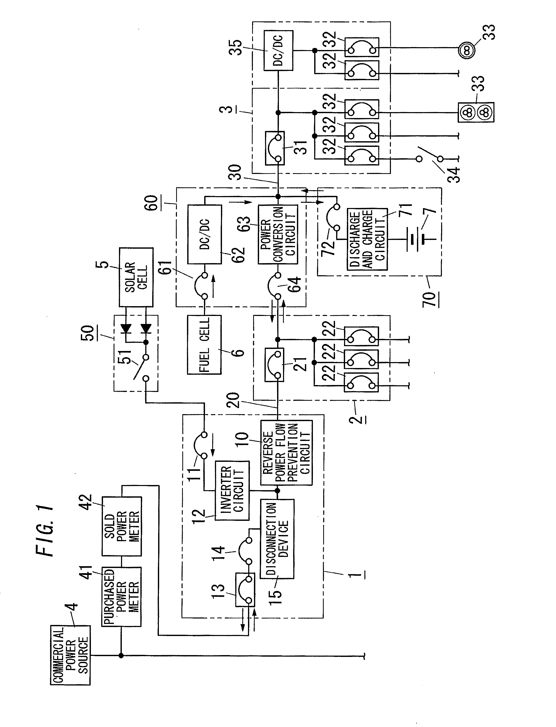
[0014]As shown in FIG. 1, the power distribution system of the present embodiment is used for distributing power to loads (electric devices) installed in a residence, and includes an AC distribution board 2 and a DC distribution board 3. The AC distribution board 2 is placed in a predetermined position in the residence, and is configured to supply AC power to an AC powered load (hereinafter, referred to as “AC load”). The DC distribution board 3 is placed in a predetermined position in the residence, and is configured to supply DC power to a DC powered load (hereinafter, referred to as “DC load”).

[0015]The AC distribution board 2 is configured to accommodate a main breaker 21 being an earth leakage circuit breaker, and a plurality of branch breakers 22. Connecting a load circuit used in AC power to the branch breaker 22 enables supplying AC power to an AC load (not shown). The main breaker 21 is interposed in the AC main power path 20 connected to a commercial power source 4. Each b...

second embodiment

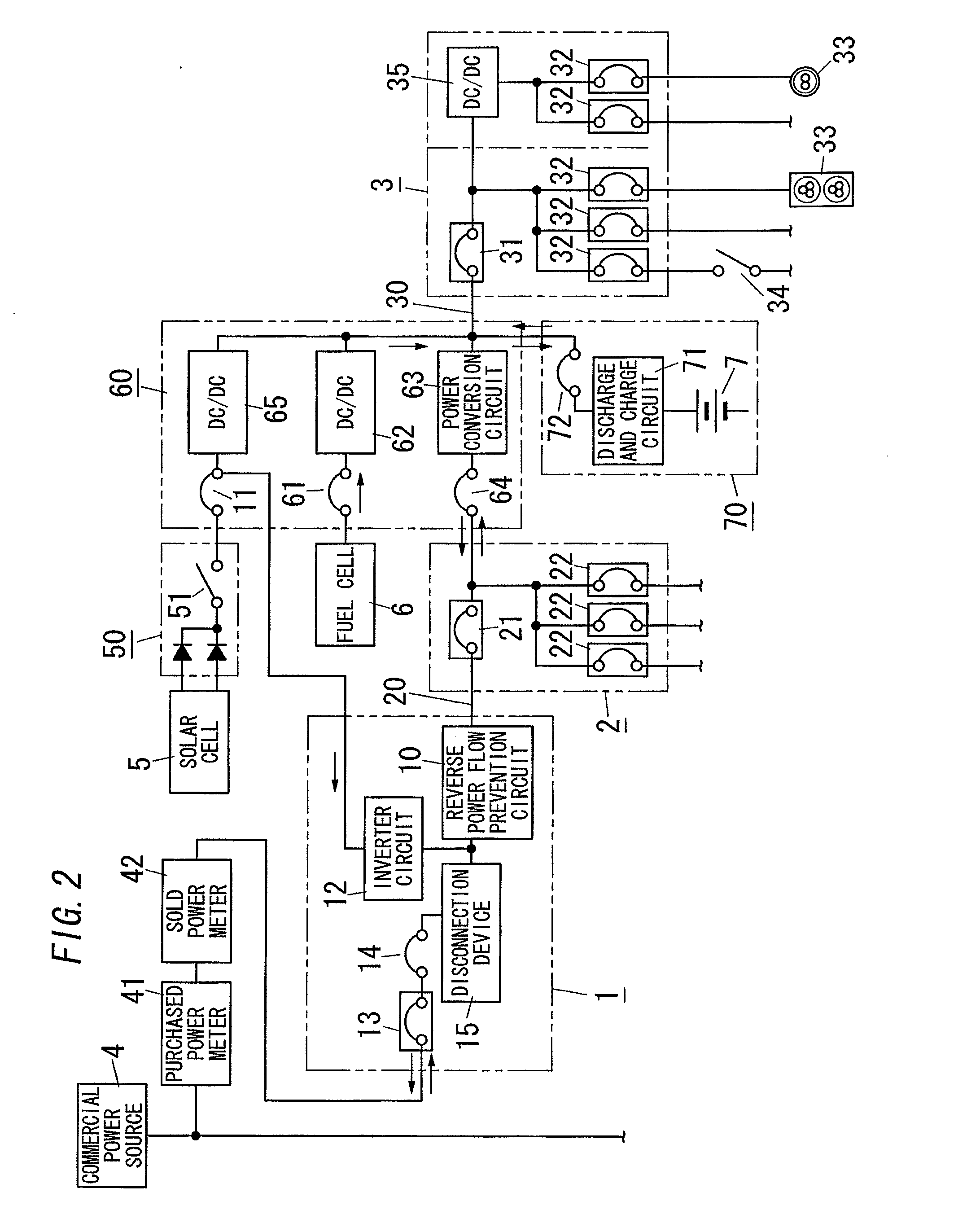
[0032]As shown in FIG. 2, the power distribution system of the present embodiment is different from the power distribution system of the first embodiment in that the solar cell 5 is connected to the DC main power path 30 without passing through the power conversion circuit 63.

[0033]In the present embodiment, the solar cell 5 is connected to a DC / DC converter 65 via the connection box 50 and the switch 11. The DC / DC converter 65 has its output terminal connected to the primary side terminal of the main breaker 31 of the DC distributed board 3. Further, the solar cell 5 is also connected to the inverter circuit 12 of the system coordination unit 1 via the switch 11 without passing through the DC / DC converter 65.

[0034]In the present embodiment, the control unit may be configured to keep turning off the switch 64 between the power conversion circuit 63 and the AC main power path 20 so as to separate the AC main power path 20 from the DC main power path 30 during the daytime that the sol...

third embodiment

[0037]As shown in FIG. 3, the power distribution system of the present embodiment is different from the power distribution system of the first embodiment in that the fuel cell 6 is connected to the AC main power path 20 without passing through the power conversion circuit 63.

[0038]In the present embodiment, the fuel cell 6 is connected to an inverter circuit 67 via a switch 66. The inverter circuit 67 is configured to convert DC supplied from the fuel cell 6 to AC to be supplied to the AC main power path 20. The inverter circuit 67 has its output terminal connected to the primary side terminal of the main breaker 21 of the AC distributed board 2. In brief, the reverse power flow prevention circuit 10 is interposed in the AC main power path 20 between the connection point of the solar cell 5 and the AC main power path 20 and the connection point of the fuel cell 6 and the AC main power path 20. The switch 11 and the inverter circuit 12 for the solar cell 5 are separated from the syst...


PUM


Abstract

A system coordination unit 1 includes a reverse power flow prevention circuit 10. When power output from a fuel cell 6 and / or a secondary cell 7 exceeds power consumed in AC loads and DC loads, the reverse power flow prevention circuit 10 prevents a reverse flow of excess power into a commercial power source 4. The reverse power flow prevention circuit 10 is interposed in an AC main power path 20 between a connection point of a solar cell 5 and the AC main power path 20 and each of a connection point of a fuel cell 6 and the AC main power path 20 and a connection point of a secondary cell 7 and the AC main power path 20. The reverse power flow prevention circuit 10 compares the power output from the fuel cell 6 and / or the secondary cell 7 with the power consumed in the AC loads and the DC loads. Upon determining that the former power is not less than the latter power, the reverse power flow prevention circuit 10 electrically interrupts the AC main power path 20. Consequently, the reverse power flow of the power generated by the fuel cell 6 and / or the secondary cell 7 into the commercial power source 4 is prevented by making use of only one reverse power flow prevention circuit 10. Therefore, in comparison with a case where each distributed power source other than a solar cell 5 is provided with a reverse current flow prevention device, the system can be implemented at a low cost.

Description

TECHNICAL FIELD[0001]The present invention relates to a power distribution system employing a solar cell and a distributed power source other than a solar cell.BACKGROUND ART[0002]In the past, there has been a system which includes a solar cell connected to a commercial power source in parallel and performs system coordination operation of supplying power to loads from the commercial power source and the solar cell. Such a system is well known as a power distribution system adopting a solar cell as a distributed power source. In such a power distribution system, during the daytime, the solar cell can generate sufficient power, and therefore generated power of the solar cell is likely to exceed consumed power and cause an excess (hereinafter referred to as “excess power”) of power. In this situation, this power distribution system can sell the excess power to a power company by feeding the excess power to the commercial power system (cf., JP 2003-189477 A).[0003]Recently, the power d...

Claims


Application Information

Patent Timeline
Patent Type & Authority Applications(United States)
IPC IPC(8): H02J4/00
CPCH02J3/381H02J3/383Y02E10/566H02J7/35Y02E10/563H02J3/387H02J2300/30H02J2300/24Y02E10/56
Inventor CYUZAWA, TAKAAKISHINAGAWA, MIKIO
Owner PANASONIC CORP
Why Eureka
Try Eureka