Systems and Methods for Alignment, Calibration and Rendering for an Angular Slice True-3D Display

a technology of true 3d and system and method, applied in image analysis, image enhancement, instruments, etc., can solve problems such as distortion of the aspect ratio of objects away from the plane of focus of true 3d

Active Publication Date: 2012-11-29
THIRD DIMENSION IP
View PDF8 Cites 69 Cited by
  • Summary
  • Abstract
  • Description
  • Claims
  • Application Information

AI Technical Summary

Benefits of technology

[0012]Therefore, there is a clear need for a method to align, calibrate and render a true 3D display, where each of the viewers' eyes not only sees a different scene, but the scene changes continuously as the viewers move their heads or change their positions from one angular location to another angular location with respect to the display screen. In one embodiment, multiple “angular slices” (scenes as viewed by a camera from a particular angular vantage point) are projected on to a viewing screen, which diffuses the angle illuminated by the projection lens projecting the scene into a particular vertical and horizontal angular slice, where the diffusion may be asymmetric. A camera is used as a feedback sensor to align the projected pixels of the angular slices with sub-pixel geometric correction and to calibrate the intensity and color across the slices for smoothing variations in intensity and color. A viewer observing the display screen will thus see a smoothly blended image (a different image for each eye and for each viewpoint) of the multiple slices. This smoothly blended image is a collection of angular slices where one projector in the true 3D display contributes one slice. A rendering method uses the alignment and calibration to generate a 2D angular slice image that drives each projector. The rendering creates a 2D angular slice image using an image projection with a horizontal focus at the projectors and a vertical focus at the viewer. Alternatively, a projection with the horizontal and vertical focus at the viewer can be used. This projection leads to some distortion in the aspect ratio of objects away from the plane of focus for the true 3D display. However, this projection allows use of images from real world cameras (either single frame or video) to drive the projectors directly without the rendering step. Finally, a control interface allows the viewer to control the amount of parallax and the focal plane of the continuously blended angular slice 3D.

Problems solved by technology

This projection leads to some distortion in the aspect ratio of objects away from the plane of focus for the true 3D display.

Method used


Image

  • Systems and Methods for Alignment, Calibration and Rendering for an Angular Slice True-3D Display
  • Systems and Methods for Alignment, Calibration and Rendering for an Angular Slice True-3D Display
  • Systems and Methods for Alignment, Calibration and Rendering for an Angular Slice True-3D Display

Examples


first embodiment

Operation—First Embodiment

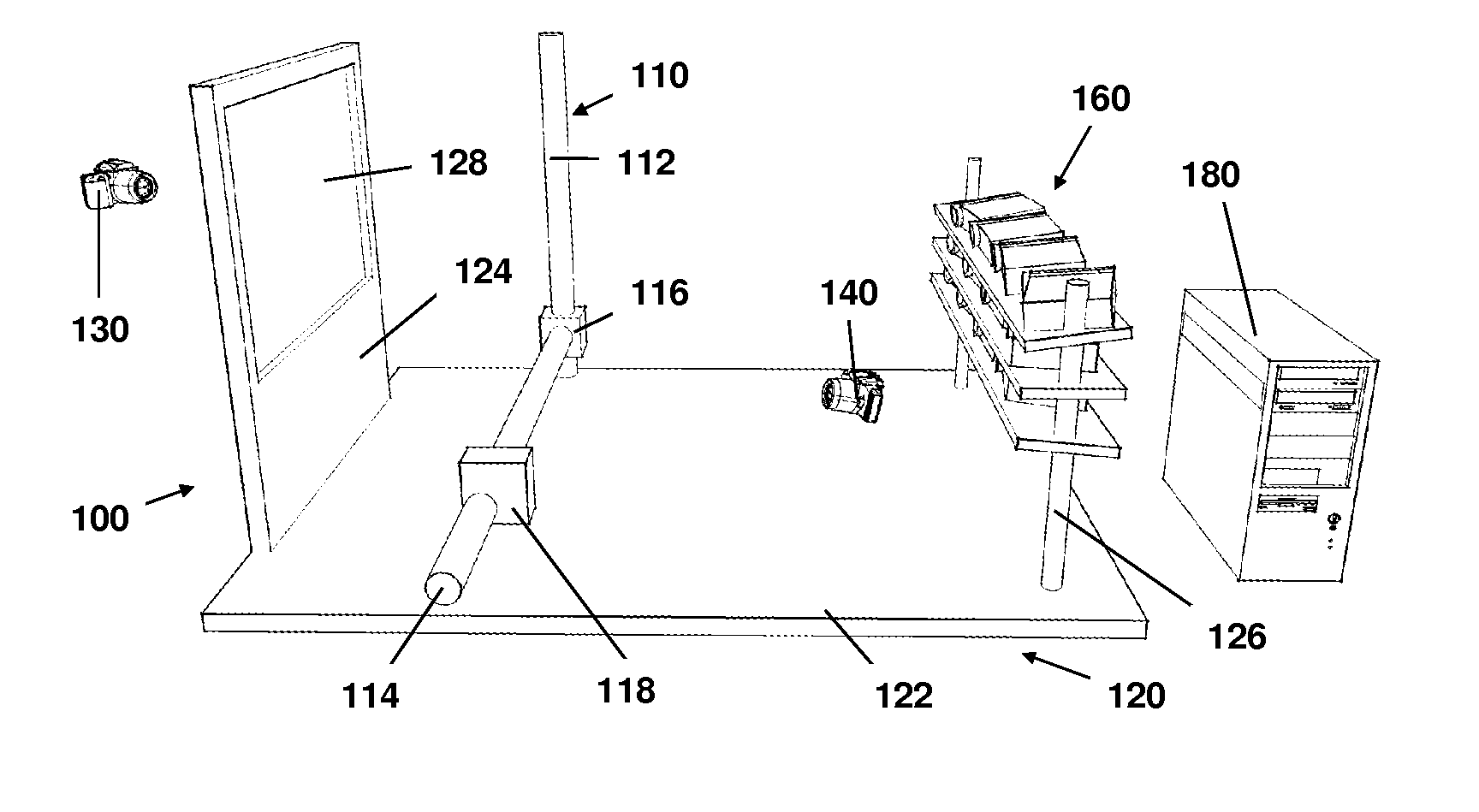
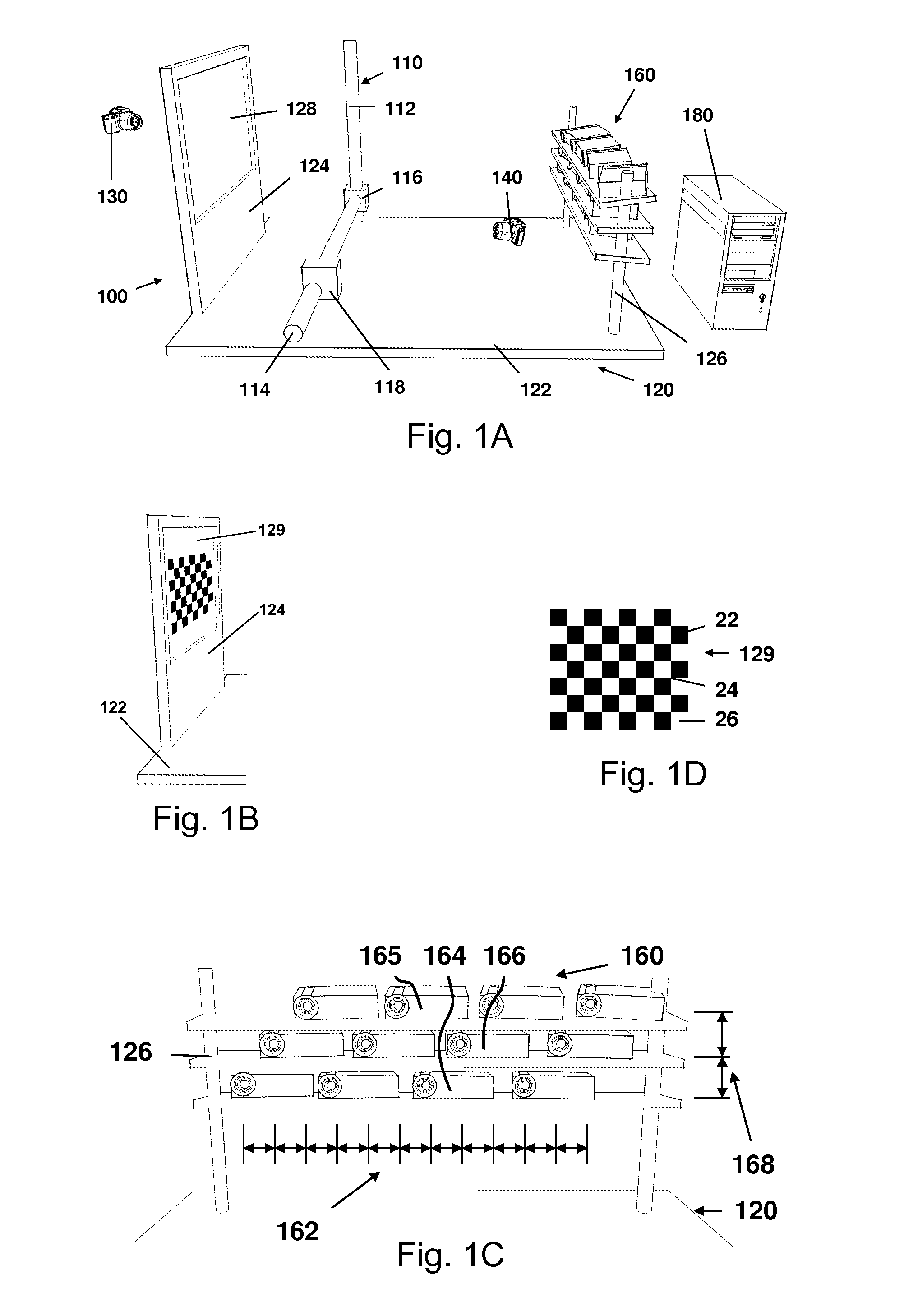
[0048]The flowchart 200 in FIG. 2 shows the steps for the alignment, calibration and rendering of 3D imagery using the display 100 from FIG. 1C. The first step in the operation is the alignment and calibration step 210. A more detailed flowchart of step 210 appears in FIG. 5A. An initial step 500 is to estimate the 3D angular geometry of the display 100. shown in FIG. 1A. Then a loop 212 is setup in the FIG. 1A computer 180 to cycle through each of the projectors 160. The loop 212 first performs a step 600 to measure the pixel alignment. This step uses the FIG. 1A camera 140 and the FIG. 1B pattern screen 129 to align with sub-pixel accuracy the projected images of the FIG. 1A projectors 160 to satisfy the FIG. 3A angular slice geometry 30. The loop 212 in step 700 next measures the intensity and color of angular slices using the camera 140 of FIG. 1A. This step measures the intensity and color variations that occur due to mismatches across the projectors 1...


PUM


Abstract

Systems and methods for calibrating a 3D display system. In one embodiment, a system includes a display screen, 2D image projectors that project 2D projection images onto the screen and a camera that captures calibration images of the screen. A computer generates the 2D projection images, which include calibration patterns, and processes the captured calibration images. The computer uses the calibration images to calculate corrections based upon the calibration images. The computer can then generate corrected 2D projection images that are projected by the 2D image projectors onto the screen to produce a substantially visually correct 3D image with continuous viewing, true horizontal parallax, and a different view for each eye within a valid viewing zone. The corrections to the images may include corrections to the geometry (including distortion, alignment, etc.) color (including intensity and related parameters).

Description

CROSS-REFERENCE TO RELATED APPLICATIONS[0001]This application claims the benefit of U.S. Provisional Patent Application 61 / 489,774, by Clarence E. Thomas, et al., filed May 25, 2011which is incorporated by reference as if set forth herein in its entirety.BACKGROUND[0002]1. Field of the Invention[0003]The present invention relates generally to the field of three-dimensional (3D) displays. More specifically, the invention relates to a system and methods of alignment, calibration and rendering for angular slice true-3D display suitable for multiple viewers without use of glasses or tracking of viewer position, where each of the viewers' eyes sees a slightly different scene (stereopsis), and where the scene viewed by each eye changes as the eye changes position (parallax).[0004]2. Related ArtThree-Dimensional Displays[0005]Over the last 100 years, significant efforts have gone into developing three-dimensional (3D) displays. To date none of these efforts have been truly satisfactory. Th...

Claims


Application Information

Patent Timeline
Patent Type & Authority Applications(United States)
IPC IPC(8): H04N17/02H04N13/04H04N13/349
CPCG06T7/0042H04N13/0425G06T2207/30204H04N13/0459H04N9/3194H04N13/0402H04N9/3147H04N9/3182H04N13/0445G06T7/73H04N13/302H04N13/327H04N13/349H04N13/363
Inventor THOMAS, CLARENCE E.PAGE, DAVID L.
Owner THIRD DIMENSION IP
Why Eureka
Try Eureka