Compound interferometer with monolithic measurement cavity

a monolithic measurement cavity and interferometer technology, applied in the field of compound commonpath interferometers, can solve the problems of difficult to achieve the measurement of the opposite side surface of opaque parts using conventional interferometry, and complicate the comparison between the measurements taken by the two measurement arms, so as to reduce undesirable cross influences

Active Publication Date: 2012-11-29
CORNING INC
View PDF9 Cites 8 Cited by
  • Summary
  • Abstract
  • Description
  • Claims
  • Application Information

AI Technical Summary

Benefits of technology

[0006]The invention, among its preferred embodiments, features a compound common-path interferometer having two measurement arms (i.e., one for each of two common-path interferometers) that are in one sense interconnected end to end for purposes of taking related measurements but are in another sense unconnected for reducing undesirable cross influences. For example, a thermally stable coupling interconnects the reference optics of the two measurement arms to provide a monolithic measurement cavity for both me

Problems solved by technology

The measurement of opposite side surfaces of opaque parts is difficult to accomplish using conventional interferometry, particularly for purposes of both measuring the two sides individually, such as for determining flatness of each, and measuring the two sides relative to each other, such as for de

Method used


Image

  • Compound interferometer with monolithic measurement cavity
  • Compound interferometer with monolithic measurement cavity
  • Compound interferometer with monolithic measurement cavity

Examples


Embodiment Construction

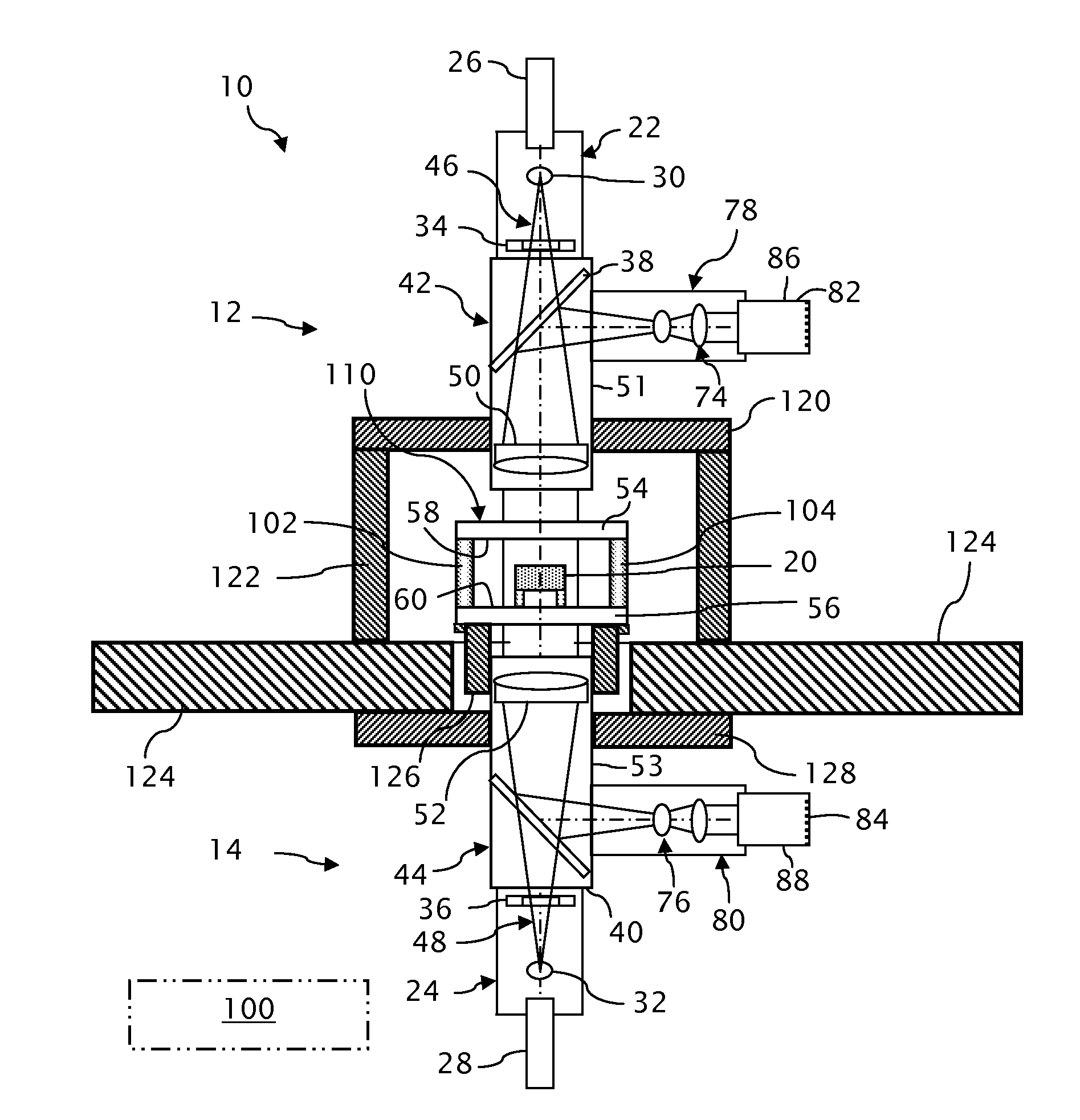
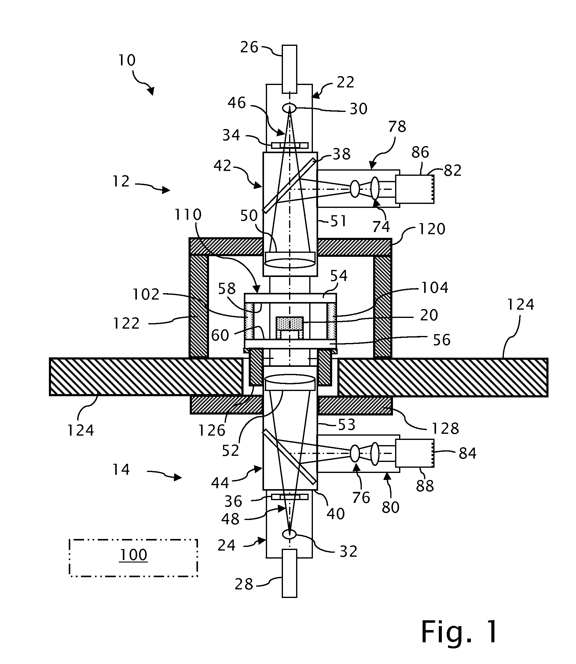
[0018]A compound common-path interferometer 10 as depicted in FIG. 1 includes an upper common-path interferometer 12 and a bottom common-path interferometer 14 for measuring opposite first and second sides 16 and 18 of an opaque test part 20 (see also FIG. 2). The opaque test part 20 can be a part that is made of materials that are not transmissive within the range of frequencies propagated by the common-path interferometers 12 and 14 or that is sufficiently diffuse to preclude the ordered transmission of such frequencies.

[0019]The upper and lower interferometers 12 and 14 include respective first and second illuminators 22 and 24, which can include customary light sources 26 and 28 and beam shapers 30 and 32 for outputting coherent first and second measuring beams 46 and 48. For example, the light sources 26 and 28 can be semiconductor diode lasers, and the beam shaping optics 30 and 32 can include beam expanders and conditioners for affecting distributions of light within the meas...


PUM


Abstract

A compound common-path interferometer including first and second measurement arms for measuring a test object is arranged so that a reference optic of the first measurement arm is disconnected from a remainder of the first measurement arm and a coupling between the reference optics of the first and second measurement arms forms a monolithic measurement cavity for maintaining reference surfaces of the reference optics at a fixed spacing and orientation. Separate supports are provided for the monolithic measurement cavity and the remainder of the first measurement arm.

Description

TECHNICAL FIELD[0001]The invention relates to compound common-path interferometers having interrelated measurement arms, particularly Fizeau interferometers in which at least one of two measurement arms has access to the Fizeau reference optics of both measurement arms.BACKGROUND OF THE INVENTION[0002]Two-sided measurement of opaque parts, including part assemblies, by interferometers involves separately measuring the two sides and relating the separate measurements to each other for making comparisons between the two sides. Part parameter comparisons include three-dimensional form, profile, flatness, parallelism, and thickness.[0003]The measurement of opposite side surfaces of opaque parts is difficult to accomplish using conventional interferometry, particularly for purposes of both measuring the two sides individually, such as for determining flatness of each, and measuring the two sides relative to each other, such as for determining parallelism and thickness. For example, separ...

Claims


Application Information

Patent Timeline
IPC IPC(8): G01B9/02
CPCG01B11/0675G01B11/161G01B11/2441G01B2290/25G01B9/02027G01B9/02057G01B9/02058G01B9/02021
Inventor FRANKOVICH, JOHN WESTONLEE, CHRISTOPHER ALANLITZENBERGER, MICHAEL JOSEPH
Owner CORNING INC
Why Eureka
Try Eureka