Augmented accuracy using large diameter shape fiber
Active Publication Date: 2019-06-20
INTUITIVE SURGICAL OPERATIONS INC
View PDF0 Cites 19 Cited by
Summary
Abstract
Description
Claims
Application Information
AI Technical Summary
This helps you quickly interpret patents by identifying the three key elements:
Problems solved by technology
Method used
Benefits of technology
[0004]One application of optical fibers that sense the shape of a flexible tool is to use shape sensing to aid in navigating a catheter through a passage in a mammalian body (e.g., through a human lung). The optical fiber used to sense shape in the catheter (an example of a flexible tool) may be embedded into the wall of the catheter so that the optical fiber does not interfere with an instrument that is inserted into the catheter. In an embodiment, the optical fiber in the wall has diameter (or cross-sectional area) that is minimized to leave a relatively large central working channel in the catheter. For this embodiment, for most of the navigation to the site of interest in the lung, an optical imaging device (e.g., a camera or a portion thereof such as lens that can collect light for image processing) is in this relatively large central channel. Since a large channel is desirable for allowing the largest possible tools and/or optical imaging devices into the catheter, and a small overall catheter diameter is desirable to allow navigation in the smallest poss
Problems solved by technology
Smaller fiber diameters reduces the accuracy of the shape sensor versus the accuracy that could be achieved if the diameter of the shape sensing fiber was larger, such as in cases where the fiber diameter is not limited by thickness of the wal
Method used
Image
Click on the blue label to locate the original text in one second.
Reading with bidirectional positioning of images and text.
Examples
Embodiment Construction
[0020]The following description is provided in relation to several examples which may share common characteristics and features. It is to be understood that one or more features of any one example may be combinable with one or more features of the other examples. In addition, any single feature or combination of features in any of the examples may constitute additional examples.
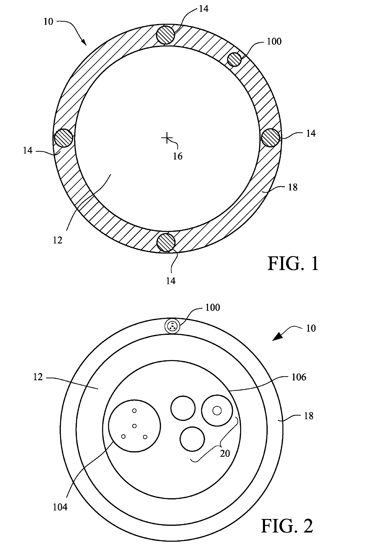
[0021]FIG. 1 illustrates a cross-section of a catheter 10 (an example of a flexible tool) with a channel 12 (or lumen) and four wires 14 arrayed within a wall 18 of the catheter used to manipulate the shape of the catheter 10. The channel 12 allows for passage of another tool, instrument or substance through the catheter 10 and the channel 12 typically will be coextensive with any portion of the catheter 10 that is flexible. The center 16 of the channel 12 is indicated. An optical fiber 100 used to sense a shape of the catheter 10 is illustrated in the wall 18.
[0022]The optical fiber 100 can be used to sense ...
PUM
Abstract
Where a flexible tool includes a tool body with a flexible portion, a distal end and a first optical fiber within the flexible portion, shape sensing can be achieved with increased accuracy by inserting or otherwise including a second optical fiber within the flexible portion. The increased accuracy can be achieved when the second optical fiber has a diameter larger than that of the first optical fiber. Once the shape of the flexible tool has been determined using at least the second optical fiber, the first optical fiber can be used for subsequent shape sensing. This may be particularly applicable where the tool includes an instrument such as an optical imaging device inserted in a channel of the tool, where not all of the width of the channel is occupied by functional components behind the operable end of the instrument.
Description
[0001]This application claims the priority and benefit of U.S. Provisional Patent Application 62 / 375,787, filed Aug. 16, 2016, entitled “AUGMENTED ACCURACY USING LARGE DIAMETER SHAPE FIBER,” which is incorporated herein by reference in its entirety.BACKGROUND[0002]Various techniques for an optical fiber and application thereof are known.[0003]For example, the following patents all discuss aspects of detecting the shape of an optical fiber, or the application of such detection: U.S. Pat. Nos. 7,781,724, 7,720,322, 8,460,236, 8,672,837, 8,567,265, all of which are hereby incorporated by reference in their entireties.BRIEF SUMMARY[0004]One application of optical fibers that sense the shape of a flexible tool is to use shape sensing to aid in navigating a catheter through a passage in a mammalian body (e.g., through a human lung). The optical fiber used to sense shape in the catheter (an example of a flexible tool) may be embedded into the wall of the catheter so that the optical fiber ...
Claims
Application Information
Patent Timeline
Application Date:The date an application was filed.
Publication Date:The date a patent or application was officially published.
First Publication Date:The earliest publication date of a patent with the same application number.
Issue Date:Publication date of the patent grant document.
PCT Entry Date:The Entry date of PCT National Phase.
Estimated Expiry Date:The statutory expiry date of a patent right according to the Patent Law, and it is the longest term of protection that the patent right can achieve without the termination of the patent right due to other reasons(Term extension factor has been taken into account ).
Invalid Date:Actual expiry date is based on effective date or publication date of legal transaction data of invalid patent.