Core catcher

a core catcher and core technology, applied in the field of core catcher, can solve the problems of insufficient cooling of the core, and possible situations, and achieve the effect of increasing the installation cost and facilitating the installation of the corium holding structur

Inactive Publication Date: 2012-11-29
KK TOSHIBA
View PDF7 Cites 8 Cited by
  • Summary
  • Abstract
  • Description
  • Claims
  • Application Information

AI Technical Summary

Benefits of technology

[0013]The present invention has been devised in view of such circumstances, and an object of the present invention is to provide a core catcher which has achieved easier installation of a corium holding structure without an increase in installation cost.
[0015]According to the present invention, installation of a corium holding structure can be made easier than before without an increase in installation cost.

Problems solved by technology

If supply of water into a reactor pressure vessel is stopped or cooling water is lost due to a rupture in piping connected to the reactor pressure vessel in a water-cooled type reactor, a reactor water level drops to expose a reactor core (which will be simply referred to as “core”, hereinafter), which may result in insufficient cooling of the core.
However, though it is extremely low probability to become a situation in which the emergency core cooling system described above does not work and other devices for injecting water into the core are not available, the situation may occur.
Under such a situation, a drawdown in the reactor water level exposes the core, and the core fails to be sufficiently cooled.
Decay heat continuously generated even after shutdown of the reactor raises fuel rod temperature, which may lead ultimately to core meltdown.
The generated non-condensable gas may pressurize the containment vessel and break the reactor containment vessel.
The melting and ablation of the concrete may break a containment vessel boundary and decrease structural strength of the containment vessel.
However, fabrication (installation) of a structure for holding a molten core such as a core catcher (which will be referred to as “corium holding structure”, hereinafter) as measures to hold a molten core by application of conventional techniques as disclosed in Patent Documents described above is not necessarily easy.
The heat resisting material needs to be laid after piping or the like serving as a cooling passage is installed, and there are installment constraints such as a need for installation space including space for the cooling passage.
Installment of a corium holding structure is thus not necessarily easy.
If a corium holding structure is installed in an existing reactor by applying conventional techniques, the existing reactor not fabricated on the premise of installment of a corium holding structure has no installation space or the existing reactor has enough space but has constraints on installation methods.
Installment of a corium holding structure is thus not necessarily easy.
The idea requires use of an expensive heat resisting material with high heat resistance which can withstand thermal ablation by high-temperature corium, which results in a cost increase for the corium holding structure.

Method used


Image

  • Core catcher
  • Core catcher
  • Core catcher

Examples


first embodiment

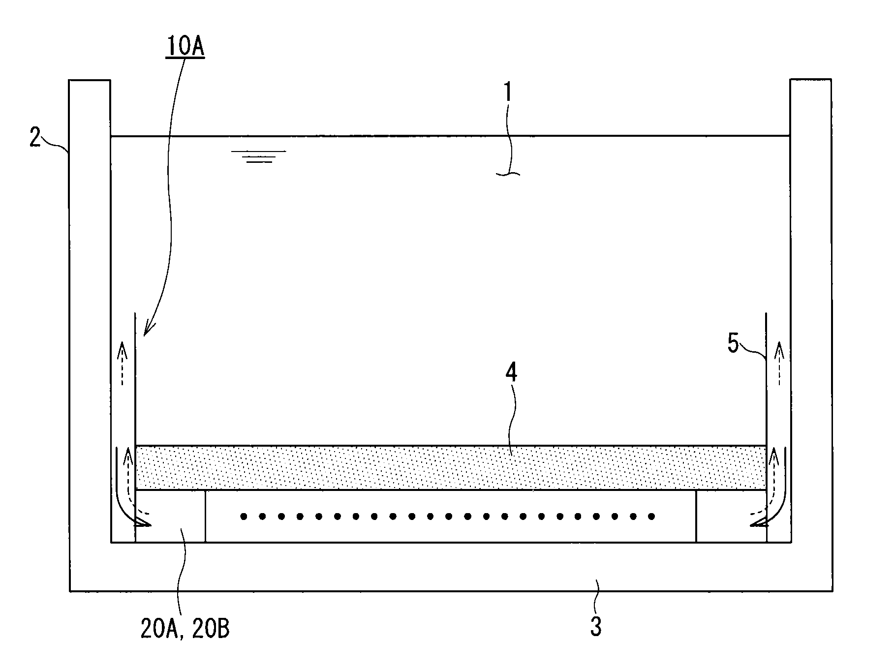
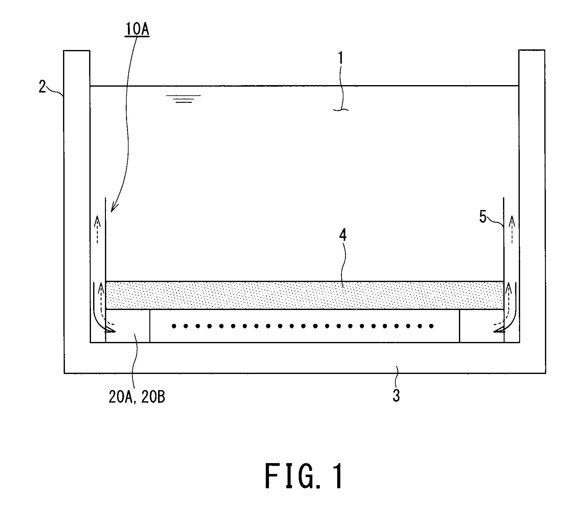
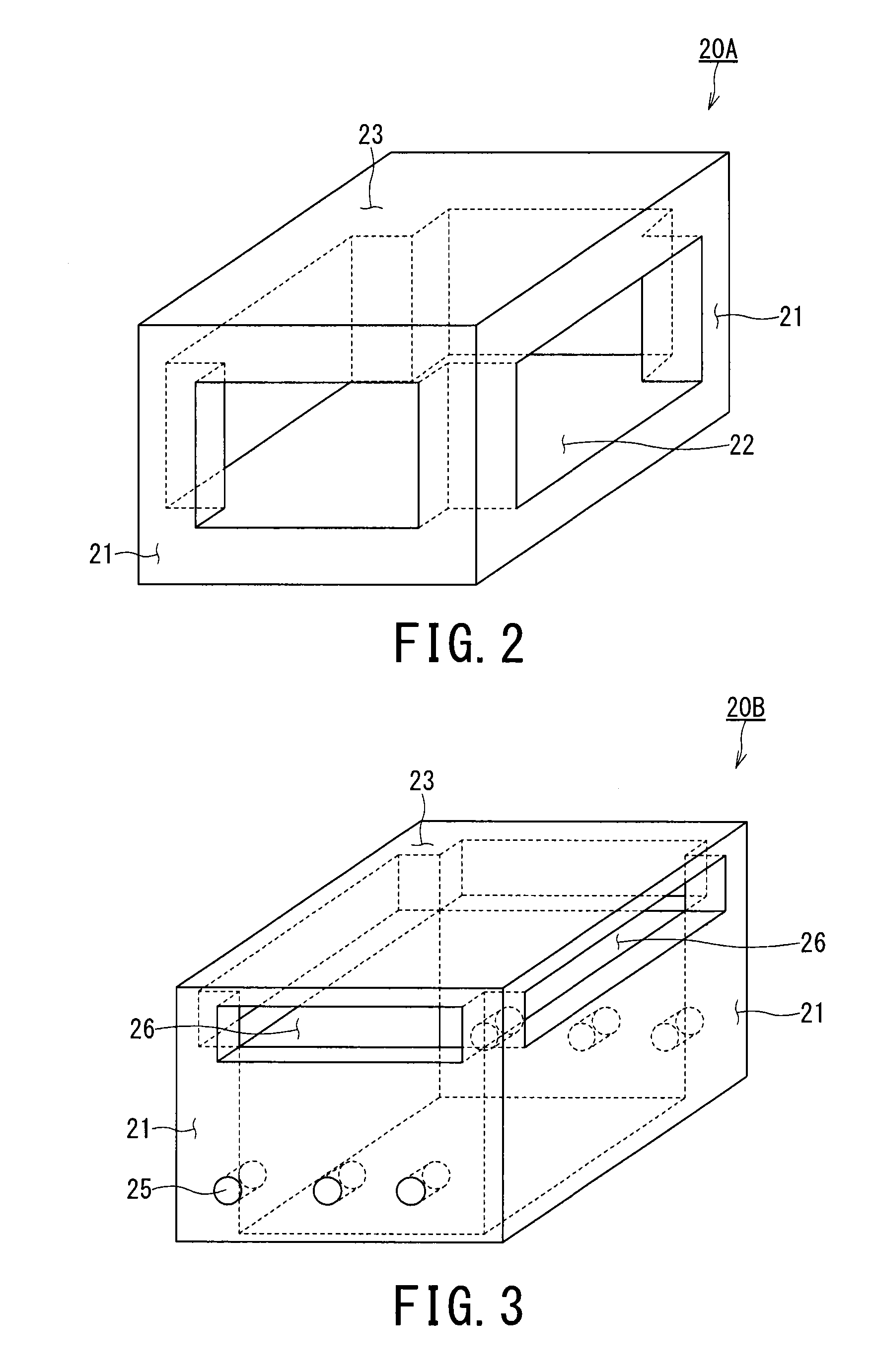
[0026]FIG. 1 is a sectional view illustrating an overview of a first corium holding apparatus (core catcher) 10A that is a core catcher, as an apparatus to catch and hold corium, according to a first embodiment of the present invention. FIG. 2 is a perspective view illustrating a configuration of a first corium holding structure (block) 20A that is an example of a corium holding structure according to the embodiment of the present invention. FIG. 3 is a perspective view illustrating a configuration of a second corium holding structure (block) 20B that is another example of a corium holding structure according to the embodiment of the present invention. It is noted that solid arrows illustrated in FIG. 1 indicate motions of a coolant 1 and that broken arrows indicate motions of vapor.

[0027]The first core catcher 10A is a corium holding structure which is constructed by arranging a plurality of corium holding structures 20 (the first corium holding structures 20A or the second corium ...

second embodiment

[0054]FIG. 4 is a local sectional view schematically illustrating, on an enlarged scale, a part of a second corium holding apparatus (core catcher) 10B that is a core catcher according to a second embodiment of the present invention.

[0055]The second core catcher 10B is different from the first core catcher 10A in that a protective portion 28 which protects corium holding structures 20 (20A or 20B) and prevents corium 4 from entering into clearance between the corium holding structures 20 is further provided on a surface for holding the corium 4, i.e., on an inner side surrounded by a riser portion 5 and on upper surfaces 23 of the corium holding structures 20.

[0056]The protective portion 28 is a component responsible for protecting the corium holding structures 20 from the corium 4 at high temperatures (about 2200° C. on average before cooling) and preventing the corium 4 from entering into clearance between the corium holding structures 20. Thus, the protective portion 28 needs to ...

third embodiment

[0059]FIG. 5 is a local sectional view illustrating, on an enlarged scale, an overview of a third core catcher 10C that is a core catcher according to a third embodiment of the present invention. It is noted that solid arrows illustrated in FIG. 5 indicate motions of a coolant 1 and that broken arrows indicate motions of vapor.

[0060]The third core catcher 10C is different from the first core catcher 10A in that a double tube structure 30 as a coolant inlet and vapor outlet unit serving both as a coolant inlet unit which introduces the coolant 1 into an inside space of corium holding structures 20 (20A or 20B) and a vapor outlet unit which discharges vapor to an outside is further provided but is not substantially different in other respects. Accordingly, same components as those in the first core catcher 10A are denoted by same reference numerals in a description of the third embodiment, and a description of the components will be omitted.

[0061]The third core catcher 10C is construc...


PUM


Abstract

A core catcher includes a holding surface that catches and holds corium and that introduces a coolant with which surroundings of the core catcher are filled into the core catcher and cool a whole of the core catcher by heat exchange with the introduced coolant. The holding surface and the cooling unit are constructed by arranging blocks which each include a polyhedron having at least one pair of parallel surfaces and having opening portion formed in a surface located in a lateral direction when a first surface that is one of the parallel surfaces is arranged as a bottom surface and are configured such that the polyhedrons communicate with each other via the opening portion when the polyhedrons are arranged adjacent in the lateral direction. The core catcher, as described above, can be achieved easier installation of the blocks without an increase in installation cost.

Description

BACKGROUND OF THE INVENTION[0001]1. Field of the Invention[0002]The present invention relates to a core catcher.[0003]2. Description of the Related Art[0004]If supply of water into a reactor pressure vessel is stopped or cooling water is lost due to a rupture in piping connected to the reactor pressure vessel in a water-cooled type reactor, a reactor water level drops to expose a reactor core (which will be simply referred to as “core”, hereinafter), which may result in insufficient cooling of the core. In preparation for such a case, the idea of automatically bringing the reactor to emergency shutdown upon receiving a signal of low water level and submerging and cooling the core by an ECCS (emergency core cooling system) injecting a coolant is adopted to prevent a meltdown accident.[0005]However, though it is extremely low probability to become a situation in which the emergency core cooling system described above does not work and other devices for injecting water into the core ar...

Claims


Application Information

Patent Timeline
Patent Type & Authority Applications(United States)
IPC IPC(8): G21C9/016G21C15/18
CPCG21C9/016Y02E30/40G21C15/18Y02E30/30
Inventor KURITA, TOMOHISATAHARA, MIKAKOMURO, MITSUOKATAGIRI, NORIYUKITANABE, MASASHI
Owner KK TOSHIBA
Why Eureka
Try Eureka