Supersonic Cooling With Pulsed Inlet and Bypass Loop

Inactive Publication Date: 2012-11-29
CAITIN
View PDF4 Cites 2 Cited by
  • Summary
  • Abstract
  • Description
  • Claims
  • Application Information

AI Technical Summary

Benefits of technology

[0011]A first claimed embodiment of the present invention is a system that includes a pump facilitating a flow of a fluid through a fluid flow path. The fluid flow path has a high pressure region and a low pressure region. As the fluid travels from the high pressure region to the low pressure region, the pump transports the fluid at a velocity that is equal to or greater than the speed of sound in the fluid. A pulsing valve creates a pulsed flow in the high pressure region of the fluid flow path, thereby reducing the mass flow rate of the fluid and corresponding energy required for a given cooling capacity. The pulsing valve operates in either a pulsing state or an always open state depending on

Problems solved by technology

Pulsing the input reduces the mass flow rate of the fluid and also r

Method used


Image

  • Supersonic Cooling With Pulsed Inlet and Bypass Loop
  • Supersonic Cooling With Pulsed Inlet and Bypass Loop
  • Supersonic Cooling With Pulsed Inlet and Bypass Loop

Examples


Embodiment Construction

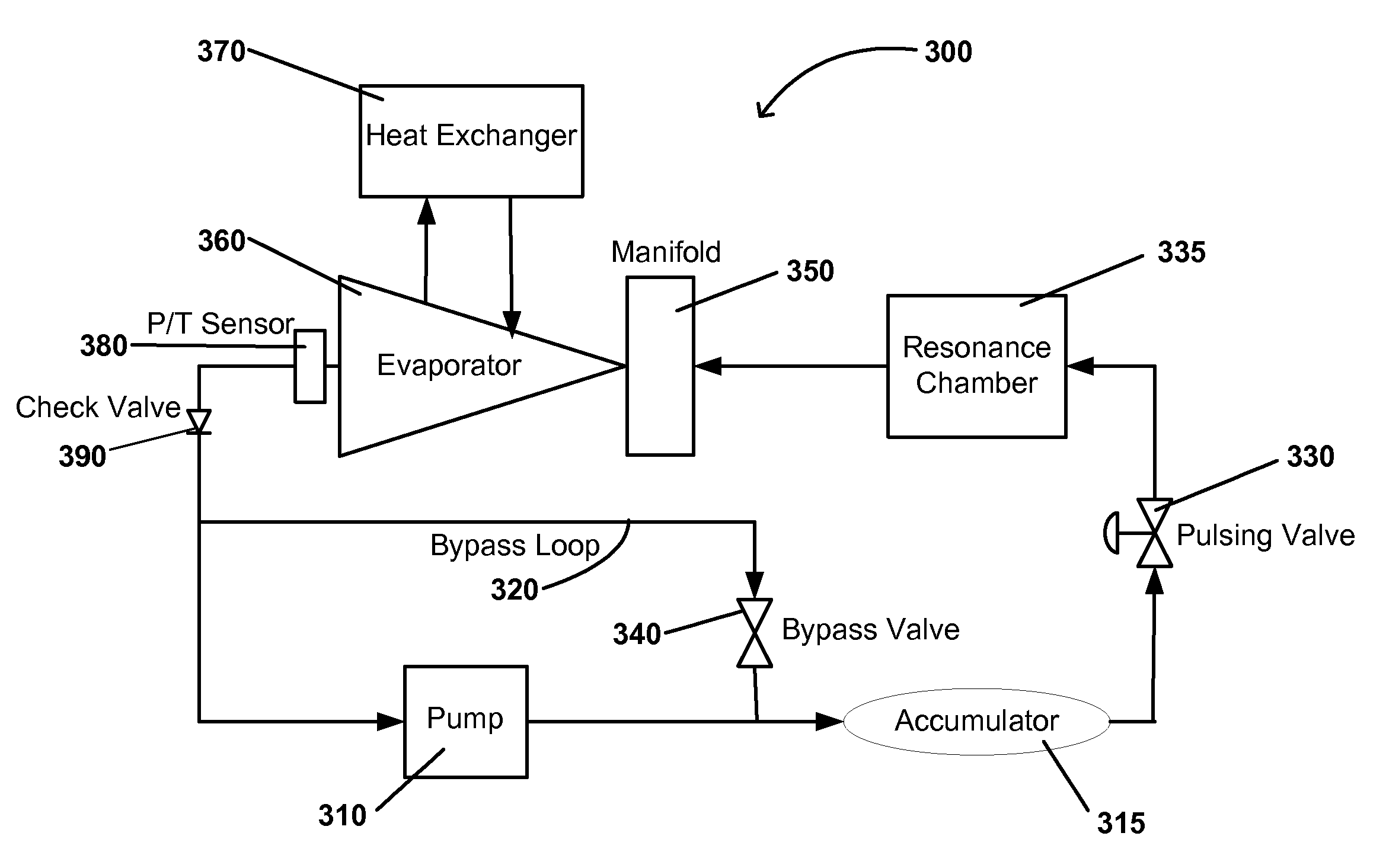
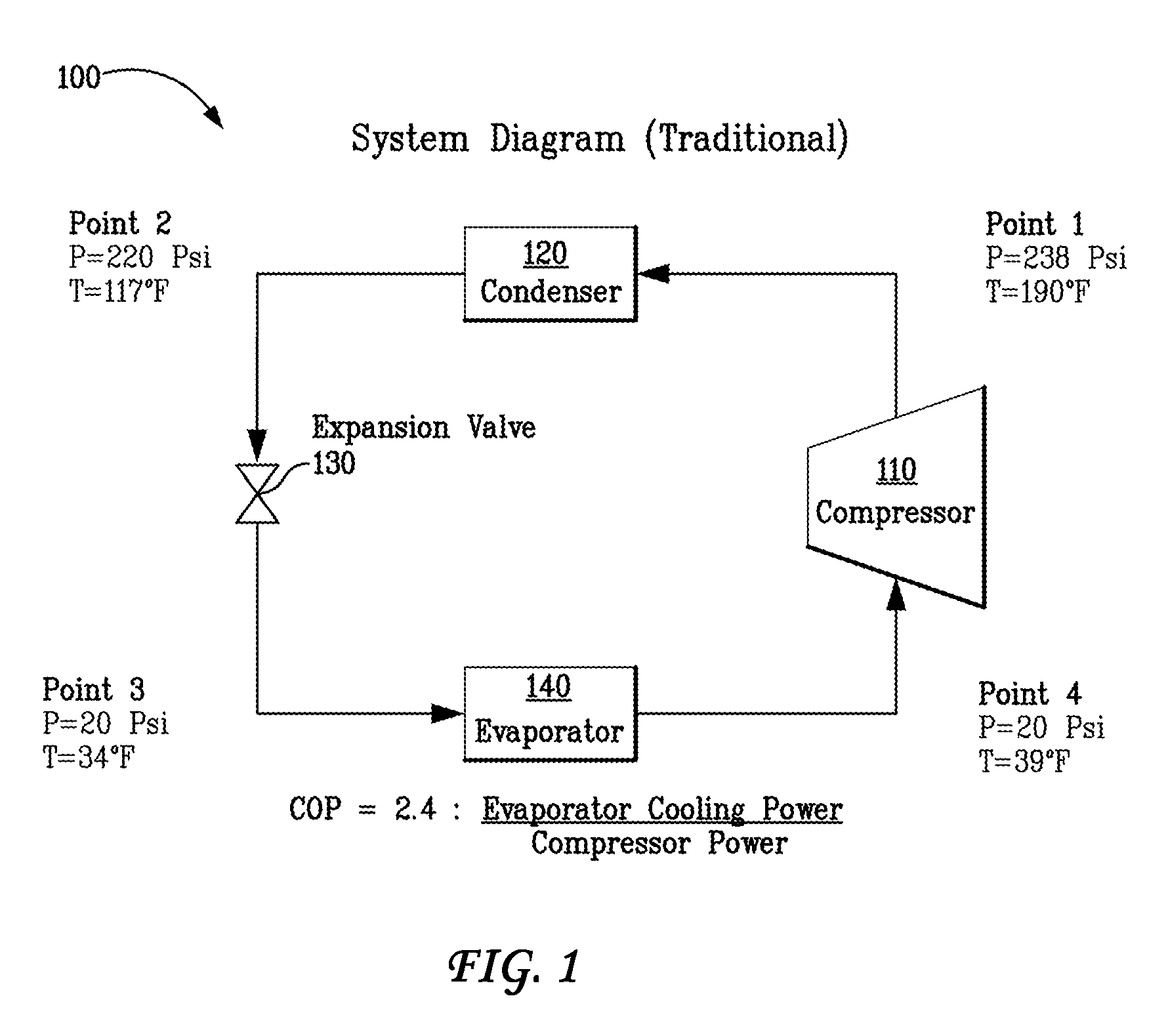
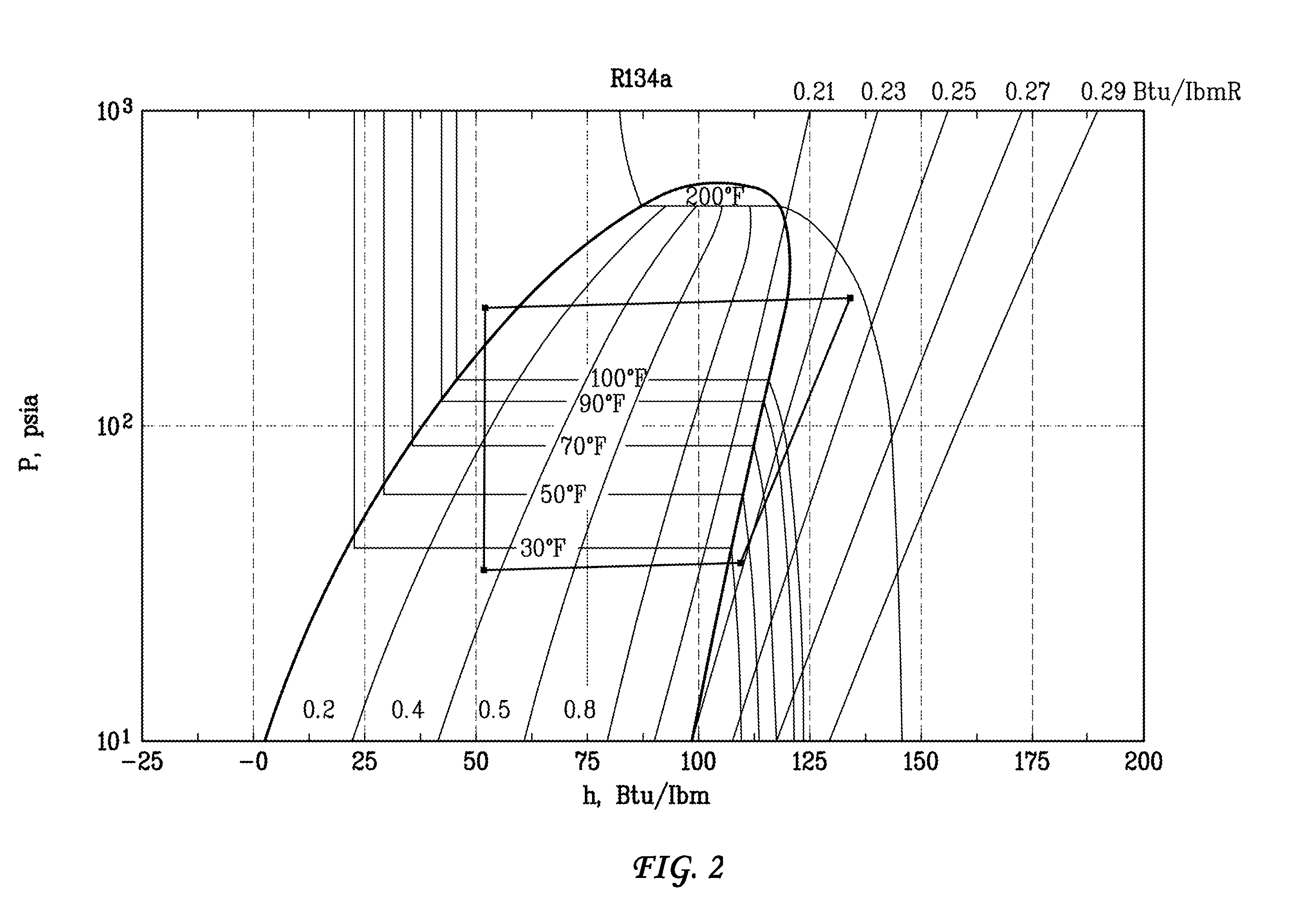
[0021]FIG. 3 illustrates an exemplary supersonic cooling system 300 in accordance with an embodiment of the present invention. FIG. 4 illustrates a pressure-enthalpy graph for a supersonic cooling system operating in accordance with FIG. 3. The supersonic cooling system 300 does not need to compress a gas as otherwise occurs at compressor 110 in a prior art vapor compression system 100 like that shown in FIG. 1. Supersonic cooling system 300 operates by pumping liquid. Because supersonic cooling system 300 pumps liquid, the compression system 300 does not require the use of a condenser 120 as does the prior art compression system 100 of FIG. 1. Supersonic cooling system 300 instead utilizes a compression wave. An evaporator of the supersonic cooling system 300 operates in the critical flow regime where the pressure in an evaporator tube or nozzle will remain almost constant and then ‘jump’ or ‘shock up’ to the ambient pressure.

[0022]The supersonic cooling system 300 of FIG. 3 recogn...


PUM


Abstract

A supersonic cooling system operates by pumping liquid without the need of a condenser. An inlet of the system may be pulsed to reduce energy required of a pump and to increase the cooling power of the system. The supersonic cooling system utilizes a compression wave in the generation of the cooling effect. The formation of the compression wave may be assisted by a resonance chamber. An evaporator of the cooling system operates in the critical flow regime.

Description

BACKGROUND OF THE INVENTION[0001]1. Field of the Invention[0002]The present invention generally relates to cooling via a supersonic fluid flow cycle. More specifically, the present invention is related to a supersonic fluid flow cycle that utilizes a pulsed inlet.[0003]2. Description of the Related Art[0004]Vapor compression systems are used in many cooling applications such as air conditioning and industrial refrigeration. A vapor compression system generally includes a compressor, a condenser, an expansion device, and an evaporator. In a prior art vapor compression system, a gas in a saturated vapor state is compressed to raise the temperature of that gas, the gas then being in a superheated vapor state. The compressed gas is then run through a condenser and turned into a liquid, and heat is rejected from the system. The condensed and liquefied gas is then taken through an expansion device, which drops the pressure and the corresponding temperature. The resulting refrigerant is th...

Claims


Application Information

Patent Timeline
IPC IPC(8): F01D25/12
CPCF25B1/00F25B9/002F25B2600/2521
Inventor GIELDA, TOMDEBUS, KRISTIANASHER, WILL
Owner CAITIN
Why Eureka
Try Eureka