Device and method for glaucoma management and treatment

Active Publication Date: 2012-11-29
ISTAR MEDICAL
View PDF10 Cites 70 Cited by
  • Summary
  • Abstract
  • Description
  • Claims
  • Application Information

AI Technical Summary

Benefits of technology

[0045]The interrogation and processing system preferably comprises a transceiver element for transmitting activation signals to the integrated intraocular device and for receiving signals corresponding to intraocular pressure measurements taken by the integrated intraocular device when activated. The interrogation and processing system may comprise a communications module for transmitting data relating to the intraocular pressure measurements to a remote location. The interrogation and processing system may be mounted in at least one of a pair of eye glasses

Problems solved by technology

However, there may be significant changes in the IOP related to the cardiac cycle, blinking, diurnally and other causes.
This makes it difficult to obtain representative values of the IOP from infrequent measurements.
Over time, this pressure increase results in irreversible damage to the optic nerve and loss of vision.
Erratic dosages, side effects and poor patient compliance are common issues.
However, the drainage plates of such devices may often be large and rigid, causing fibrotic reactions with the surrounding tissue that can progressively reduce effectiveness.
Mismatches in plate to sclera geometry can cause chronic microtrauma problems.
Whilst more recent drain devices are of smaller size they are still rigid with the potential for trauma during insertion and in subsequent use.
Howev

Method used


Image

  • Device and method for glaucoma management and treatment
  • Device and method for glaucoma management and treatment
  • Device and method for glaucoma management and treatment

Examples


first embodiment

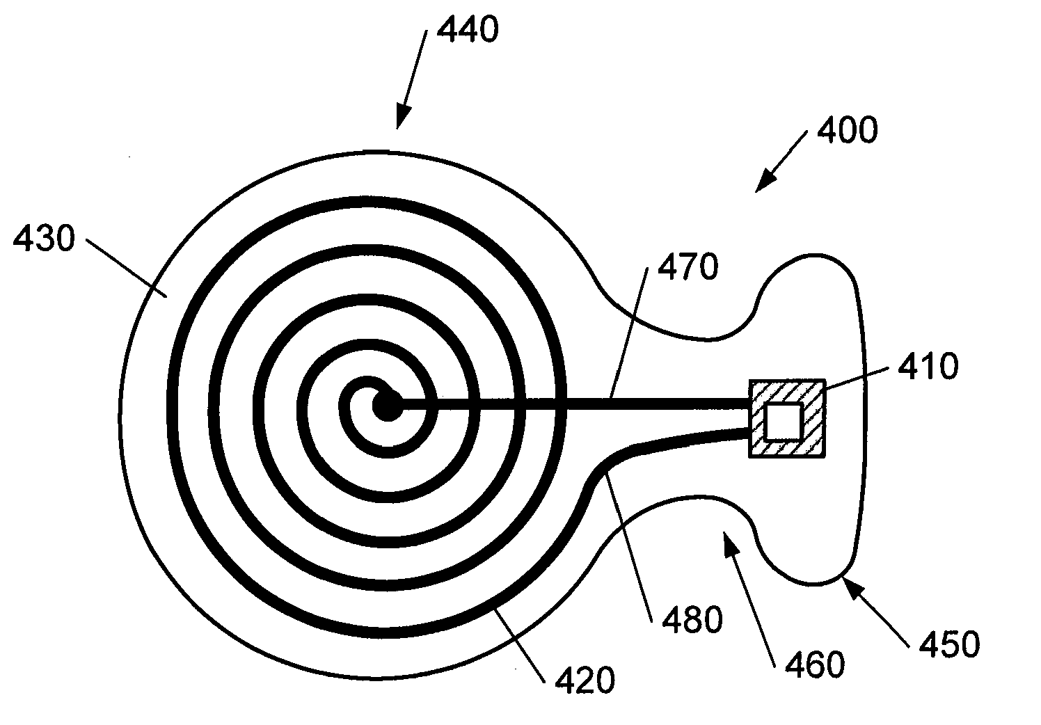
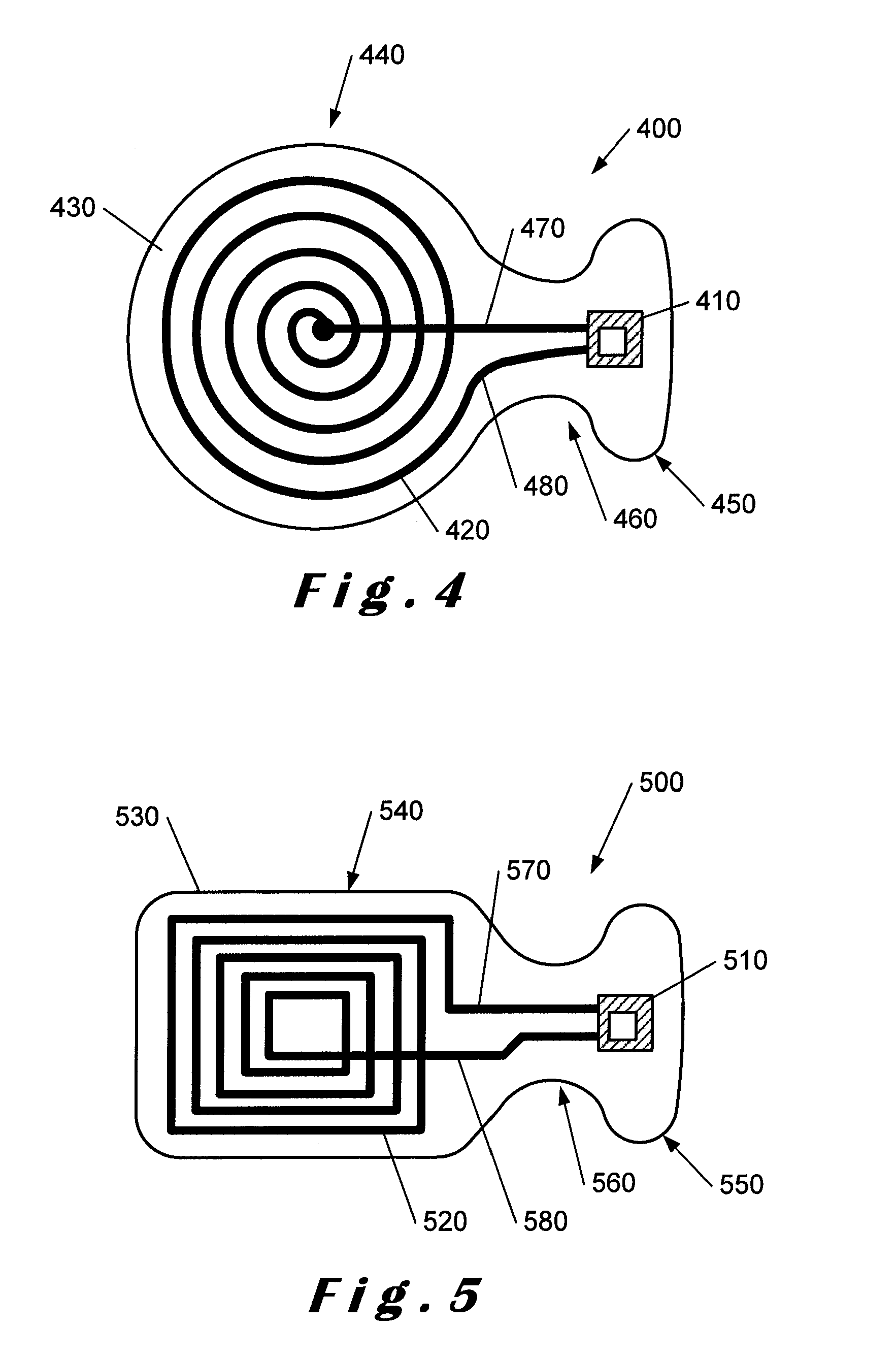
[0090]In FIG. 4, a plan view of a combined IOP sensor and glaucoma drainage device 400 in accordance with the present invention is shown. The device 400 comprises an IOP sensor element 410 connected to an antenna element 420 as shown. The IOP sensor element 410 also includes a signal processor (not shown) as will be described in more detail below. The IOP sensor element 410 and the antenna element 420 are located between layers of a porous biocompatible material 430, for example, the porous biocompatible material as described above. This is described in more detail with reference to FIGS. 6 to 8 below. The biocompatible material 430 defines the overall shape of the device 400. In this embodiment, the antenna element 420 is shown as having a substantially circular profile.

[0091]Leads 470, 480 are provided for connecting the IOP sensor element 410 with the antenna element 420 as shown. As shown, the leads 470, 480 pass from the footplate portion 450 to the body portion 440 through the...

second embodiment

[0096]In FIG. 5, a plan view of a combined IOP sensor and glaucoma drainage device 500 is shown. The device 500 comprises an IOP sensor element 510 connected to an antenna element 520 as shown. The IOP sensor element 510 also includes a signal processor (not shown) as will be described in more detail below. The IOP sensor element 510 and the antenna element 520 are located between layers of the porous biocompatible material 530 as described above. This is described in more detail with reference to FIGS. 6 to 8 below. The biocompatible material 530 defines the overall shape of the device 500. In this embodiment, the antenna element 520 is shown as having a substantially rectangular profile.

[0097]Leads 570, 580 are provided for connecting the IOP sensor element 510 with the antenna element 520 as shown. As shown, the leads 570, 580 pass from the footplate portion 550 to the body portion 540 through the neck portion 560.

[0098]As shown, the device 500 comprises a substantially rectangul...


PUM


Abstract

Described herein is a device for glaucoma treatment and monitoring that comprises a combination of an intraocular pressure (IOP) sensor and a glaucoma drainage device. The device comprises an IOP sensor and an inductive antenna mounted within a porous biocompatible material that forms the drainage path. The IOP sensor is mounted in a footplate portion of the device and is mountable in the anterior chamber of an eye. The footplate portion is connected to a body portion that houses the spiral antenna by a neck portion which retains the footplate portion in a suitable position within the anterior chamber. Due to its size, the footplate portion housing the IOP sensor can readily be inserted into the anterior chamber with the body portion housing the spiral antenna located outside of the anterior chamber in a sub-scleral space to disperse the aqueous humour.

Description

BACKGROUND[0001]1. Technical Field[0002]The present invention relates to improvements in or relating to glaucoma management and treatment, and is more particularly concerned with glaucoma devices that integrate both intraocular pressure sensors and glaucoma drainage devices.[0003]2. Description of the Related Art[0004]The mammalian eye comprises an anterior chamber located between the cornea and the iris and lens. This chamber is filled with a fluid known as aqueous humour.[0005]A trabecular meshwork, comprising a plurality of microscopic passageways, is located in the angle between the iris and the cornea. In the normal human eye, aqueous humour is generated at a constant rate, typically about 2.7 microlitres per minute (μl / min), by the ciliary body behind the iris. This aqueous humour flows past the lens and iris and then exits via the trabecular meshwork and is returned to the circulatory system.[0006]The intraocular pressure (IOP) maintaining this flow in the normal eye tends to...

Claims


Application Information

Patent Timeline
IPC IPC(8): A61B3/16A61M1/00
CPCA61B5/0031A61B3/16A61F9/00781
Inventor MARSHALL, ANDREW J.MAGINNESS, MAX G.ALVAREZ, MICHEL
Owner ISTAR MEDICAL
Why Eureka
Try Eureka