Process for producing components having regions of differing ductility

a technology of ductility and production process, applied in the direction of quenching device, furnace type, shaping tool, etc., can solve the problems of high stress on spot-welded connections, affecting the quality of sheet steel components, and requiring expensive sealing treatment to control them. , to achieve the effect of sufficient cathodic corrosion protection

Inactive Publication Date: 2012-12-06
VOESTALPINE METAL FORMING
View PDF3 Cites 35 Cited by
  • Summary
  • Abstract
  • Description
  • Claims
  • Application Information

AI Technical Summary

Benefits of technology

[0019]2. Providing enough austenitizing time for complete through-hardening of a plate with a galvanized starting material of 22MnB5 connected to a plate component B composed of a respectively galvanized soft deep-drawing steel, a micro-alloyed steel, a carbon-manganese steel, or a dual-phase steel while producing a sufficient cathodic corrosion protection during the press hardening.
[0021]4. Providing enough austenitizing time for complete through-hardening of plates A and B while producing a sufficient cathodic corrosion protection.

Problems solved by technology

Patchwork blanks have the disadvantage that the spot-welded connections are subjected to high stresses during shaping and can sometimes even fracture.
In addition, the gap that is present between the sheet metal layers can lead to corrosion problems; controlling these requires an expensive sealing treatment.
Furthermore, the transition between the individual thickness regions is relatively abrupt in both tailored blanks and patchwork blanks.
This can result in undesirable stress peaks in the immediate transition region.
Although a significant weight reduction is achieved with tailored and patchwork blanks, the corrosion protection is relatively expensive.

Method used


Image

  • Process for producing components having regions of differing ductility
  • Process for producing components having regions of differing ductility
  • Process for producing components having regions of differing ductility

Examples


Embodiment Construction

[0027]The invention offers several process options.

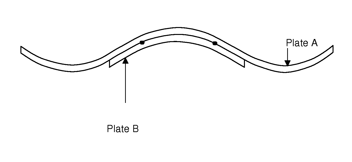
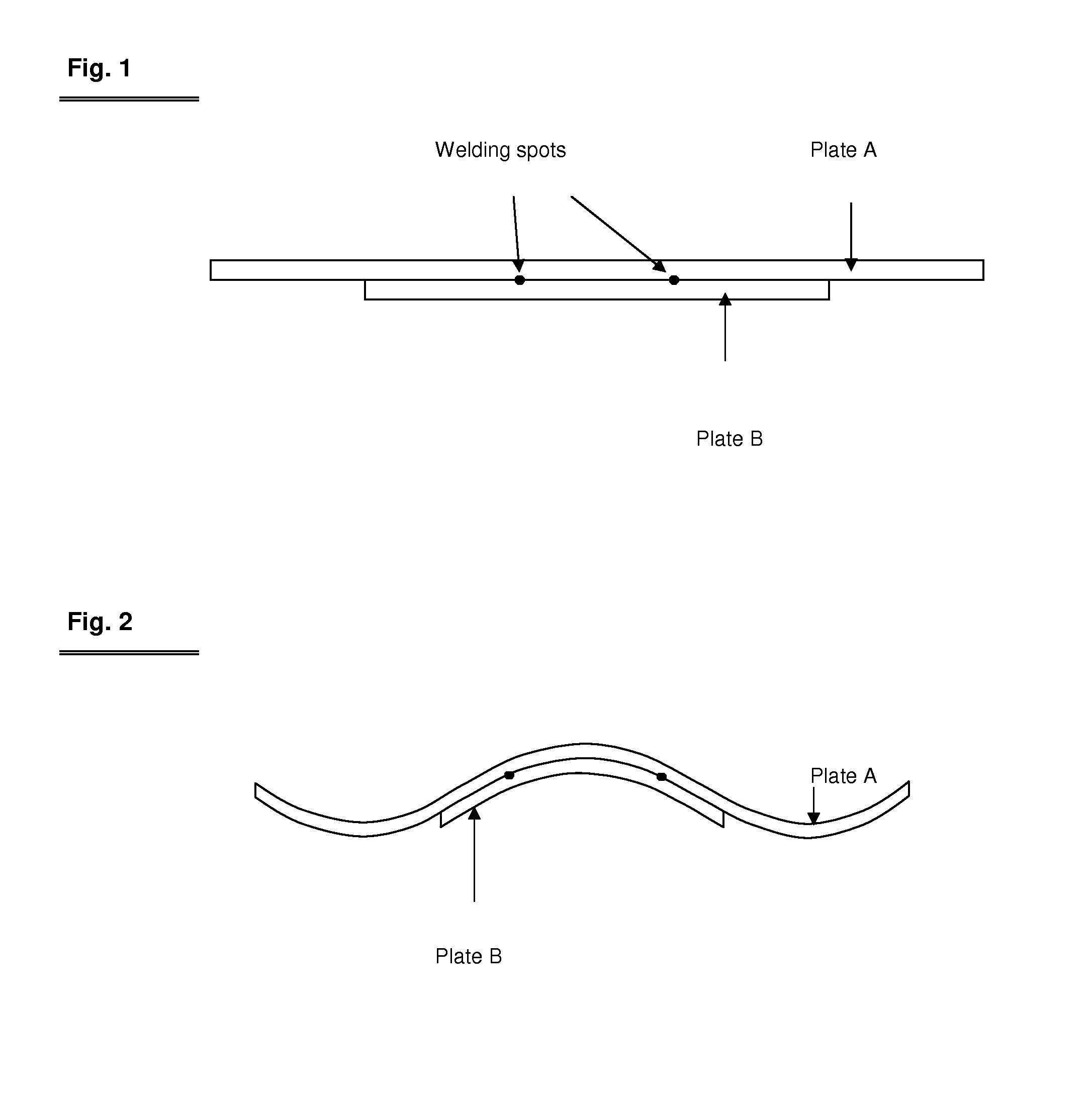
[0028]In process option 1, the cold-produced component (FIG. 2) composed of the joined individual plates A and B is heated in the furnace at approx. 900° C. until the larger component A has reached the austenitizing temperature in the regions in which it is not resting against the smaller component B.

[0029]In the regions in which components A and B are joined, the component has a higher mass to be heated.

[0030]This makes it possible, with the same furnace residence time, for region B of the component to not reach the austenitizing temperature while region A is heated to the austenitizing temperature due to its single sheet thickness and therefore lower mass.

[0031]The component is then cooled and press hardened in a press hardening die.

[0032]After the press hardening, the component has a more ductile material structure in region B because it did not reach the austenitizing temperature in the furnace.

[0033]Depending on the selected fu...


PUM

PropertyMeasurementUnit
temperatureaaaaaaaaaa
austenitizing temperatureaaaaaaaaaa
tensile strengthaaaaaaaaaa

Abstract

The invention relates to a process for producing sheet steel components having regions of differing ductility, in which either a sheet metal plate composed of a hardenable steel alloy is used to produce a component by deep-drawing and the deep-drawn component is then at least partially austenitized by a heat treatment and subsequently quench hardened in a die or the plate is at least partially austenitized by a heat treatment and shaped in the hot state, and is quench hardened during or after this, with the sheet metal plate having a zinc-based cathodic corrosion protection coating, characterized in that in regions of a desired higher ductility of the component, at least one additional sheet is attached to the plate, situated so that during the heat treatment, the plate is heated to a lesser degree there than in the remaining region.

Description

FIELD OF THE INVENTION[0001]The invention relates to a process for producing sheet steel components.BACKGROUND OF THE INVENTION[0002]In automotive construction, the use of sheet metal products—preferably composed of sheet steel—that vary in thickness and material quality is on the rise. This makes it possible to reduce the weight of vehicle body components while adapting the material used to their functions. Body components of this kind include, for example, A, B, and C pillars, bumpers and their cross members, roof frames, side impact members, exterior body parts, etc.[0003]In this connection, the prior art uses so-called tailored blanks. These are plates that are welded together out of a plurality of sheet metal pieces with the same or different sheet thicknesses and material qualities. The use of so-called patchwork blanks is also known. These are plates of varying thicknesses and material qualities that are placed parallel to one another.[0004]In the latter process, the sheets a...

Claims


Application Information

Patent Timeline
Patent Type & Authority Applications(United States)
IPC IPC(8): B21D31/00B21J15/02
CPCB21D22/20B21D22/208B21D35/006B21D37/16B21D53/88Y10T29/49956B32B15/013C21D1/673C21D8/0494C21D9/48C21D2221/00B32B15/011
Inventor HARTMANN, DIETERWIEMANN, MARCUSSOMMER, ANDREAS
Owner VOESTALPINE METAL FORMING
Why Eureka
Try Eureka