
Muffler for Internal Combustion Engine

a technology for internal combustion engines and mufflers, which is applied in the direction of machines/engines, mechanical equipment, gas passages, etc., can solve the problems of affecting the noise generation of standing waves, so as to reduce the generation of standing waves and reduce exhaust noise. , the effect of large capacity

Active Publication Date: 2012-12-06
FUTABA IND CO LTD
View PDF12 Cites 5 Cited by
  • Summary
  • Abstract
  • Description
  • Claims
  • Application Information

AI Technical Summary

Benefits of technology

The present invention aims to provide a muffler for an internal combustion engine that can suppress the weight increase and the impact on the layout caused by the large capacity of the main muffler or the addition of a sub muffler.

Problems solved by technology

In this regard, depending on lengths of exhaust pipes, silencing performance with respect to a low-frequency noise may be deteriorated because of an influence of the standing wave generated within each of these exhaust pipes.
The low-frequency noise causes a muffled sound inside a vehicle, and this muffled sound is a factor of giving an uncomfortable feeling to a passenger in the vehicle.

Method used


Image

  • Muffler for Internal Combustion Engine
  • Muffler for Internal Combustion Engine
  • Muffler for Internal Combustion Engine

Examples


Embodiment Construction

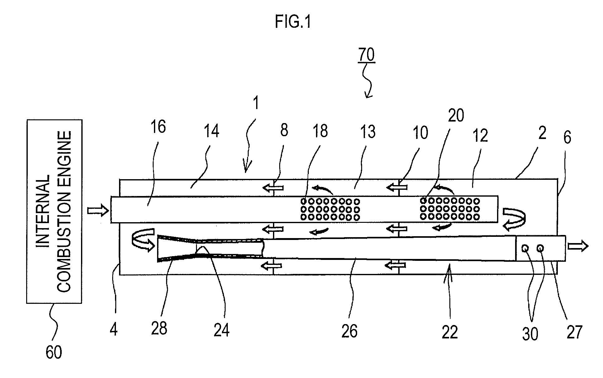
[0020]Hereinafter, an embodiment for carrying out the present invention will be described in detail with reference to the drawings.

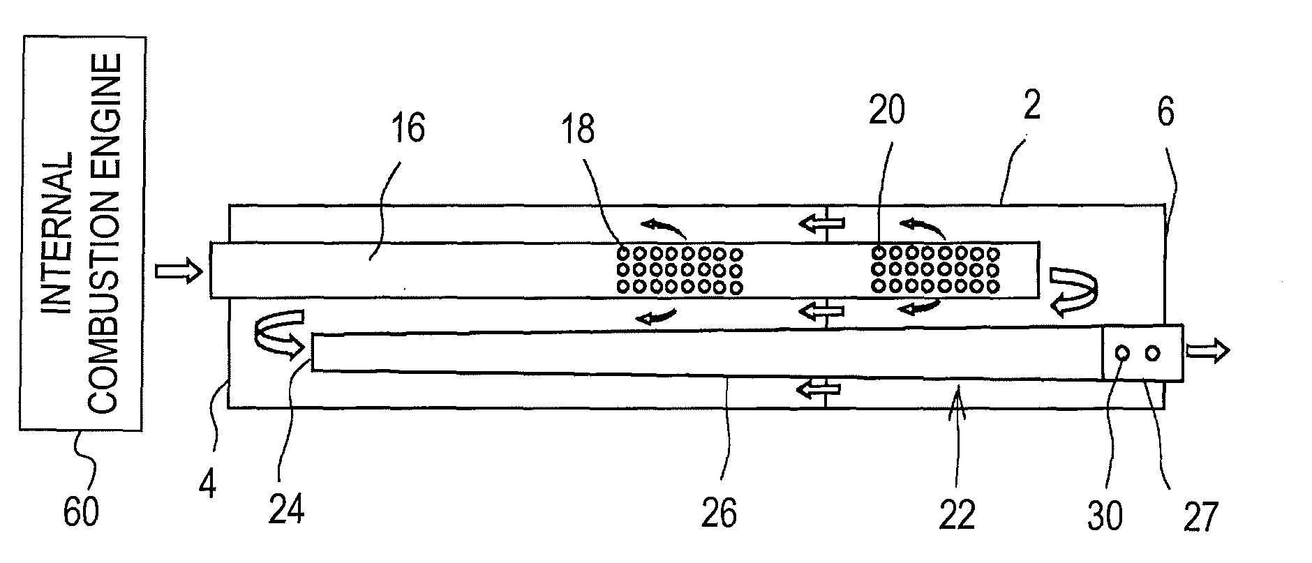
[0021]As shown in FIG. 1, a muffler 70 for an internal combustion engine is provided with an outer shell 1, an inlet pipe 16, and an outlet pipe 22.

[0022]The outer shell 1 includes a cylindrical tube part 2, and sidewall parts 4 and 6. The sidewall parts 4 and 6 close both ends of the tube part 2. The outer shell 1 is formed to have a hollow thereinside.

[0023]Inside the hollow of the outer shell 1, partition walls 8 and 10 are provided. The tube part 2 is divided by the partition walls 8 and 10 into a plurality of a first expansion chamber 12 to a third expansion chamber 14.

[0024]The inlet pipe 16 penetrates through the sidewall part 4 at one side of the outer shell 1 and is inserted into the hollow. The inlet pipe 16 penetrates through the partition walls 8 and 10 to pass through inside the third expansion chamber 14 and the second expansion chamber 13;...


PUM


Abstract

A muffler for an internal combustion engine includes an outer shell, an inlet pipe, an outlet pipe, and at least one constricted part. The at least one constricted part is provided in at least one of the inlet pipe and the outlet pipe on an open side thereof opening toward an inside of the outer shell. The at least one constricted part has a cross-sectional area smaller than a cross-sectional area of the at least one of the inlet pipe and the outlet pipe, which is provided with the at least one constricted part.

Description

CROSS-REFERENCE TO RELATED APPLICATIONS[0001]This international application claims the benefit of Japanese Patent Application No. 2010-020311 filed Feb. 1, 2010 in the Japan Patent Office, and the entire disclosure of Japanese Patent Application No. 2010-020311 is incorporated herein by reference.TECHNICAL FIELD[0002]The present invention relates to a muffler for an internal combustion engine, which is provided in an exhaust-gas flow path in the internal combustion engine to reduce exhaust noise.BACKGROUND ART[0003]Conventionally, as disclosed in Patent Document 1, in an exhaust-gas flow path of an internal combustion engine, an exhaust manifold, a catalytic converter, a sub muffler, a main muffler, and a tail pipe are disposed in the exhaust-gas flow path and installed in a space under a floor of a vehicle.[0004]In the space under the floor of the vehicle, not only devices of exhaust system, but also many components of the vehicle, such as a propeller shaft, a cross member, a side ...

Claims


Application Information

Patent Timeline
Patent Type & Authority Applications(United States)
IPC IPC(8): F01N13/08
CPCF01N1/083F01N1/084F01N1/085F01N1/081F01N2470/02F01N2470/30F01N1/086
Inventor KAINUMA, KATSUHIKO
Owner FUTABA IND CO LTD
Learn More