Split fitting for pipe

a technology of pipe fittings and split ends, which is applied in the direction of pipes/joints/fittings, pipe elements, mechanical equipment, etc., can solve the problems of high cost of sidebar stock, most prone to imperfections upon inspection, and high cost of traditional segment fabrication process, etc., to achieve easy sealing and welding, easy and less expensive manufacturing process, and less weight

Active Publication Date: 2012-12-06
PIPE LINE DEVMENT
View PDF3 Cites 5 Cited by
  • Summary
  • Abstract
  • Description
  • Claims
  • Application Information

AI Technical Summary

Benefits of technology

[0007]The invention provides an improved pipe repair fitting of the split sleeve or ring type. With the invention, conventional sidebars or flanges at the split plane are eliminated. The disclosed fitting of the invention is easier and less expensive to manufacture, weighs less, can be installed in confined spaces, and can be more easily seal welded than traditional types of split fittings.
[0008]As disclosed, segment halves of the fitting are each formed with cylindrical walls of generally uniform thickness. This simple structure permits their rough fabrication in a press brake without the need for attaching sidebars and all of the complications and expense attendant to a weldment. At each of their arcuate ends, the segment halves are machined with at least one precision formed internally threaded hole. The threaded holes of opposed arcuate ends of a pair of segment halves are precisely aligned. The threads are formed so that when the segments are properly registered with one another, the threads of one hole and the threads of an opposed hole lie on a common helix. The disclosed relationship of the threads allows a threaded bolt or stud holding the segments together to employ the walls of the segments on both sides of the split plane to function as the equivalent of a nut but without the need for such nuts and the additional space they would require.
[0009]Preferably one of the pair of aligned threaded holes is blind, while the opposing hole in the opposite segment is similarly closed, but for a reduced diameter hole that receives a tool for turning the bolt. Further, preferably one of the holes is deep enough to fully or substantially fully receive an associated bolt before the segments are mated together. Once the segments are in proper registration, the bolts can be extended from one threaded hole into the opposing threaded hole to thereby mechanically join the segments together. With the bolts initially received in the deep holes, they are protected in transit and are not susceptible to being dropped during installation, which is particularly important in underwater applications.

Problems solved by technology

The traditional segment fabricating process is expensive for a variety of reasons.
Because of its thickness, particularly for large pipe fittings, the stock used for making the sidebars is costly and is cut with oxygen acetylene rather than a laser.
Typically, the initial root pass is most prone to show imperfections upon inspection.
Regulations can impose the burden on the manufacturer of the repair fitting to record the source of the various steel parts, the welding procedure, the welder, and the date when the fitting component was produced.
Weight is reflected by added material costs, shipping and handling costs, as well as installation costs.
The overall physical size of the fitting requires correspondingly large equipment for finish machining and can make it difficult or impossible to install at a particular site.
Where, after installation, the fitting is coated with a protective material, the sidebars and bolts extending through the sidebars complicate the coating process.
Further, bolts extending through the sidebars are difficult to seal weld, particularly when inverted and under water.

Method used


Image

  • Split fitting for pipe
  • Split fitting for pipe
  • Split fitting for pipe

Examples


Embodiment Construction

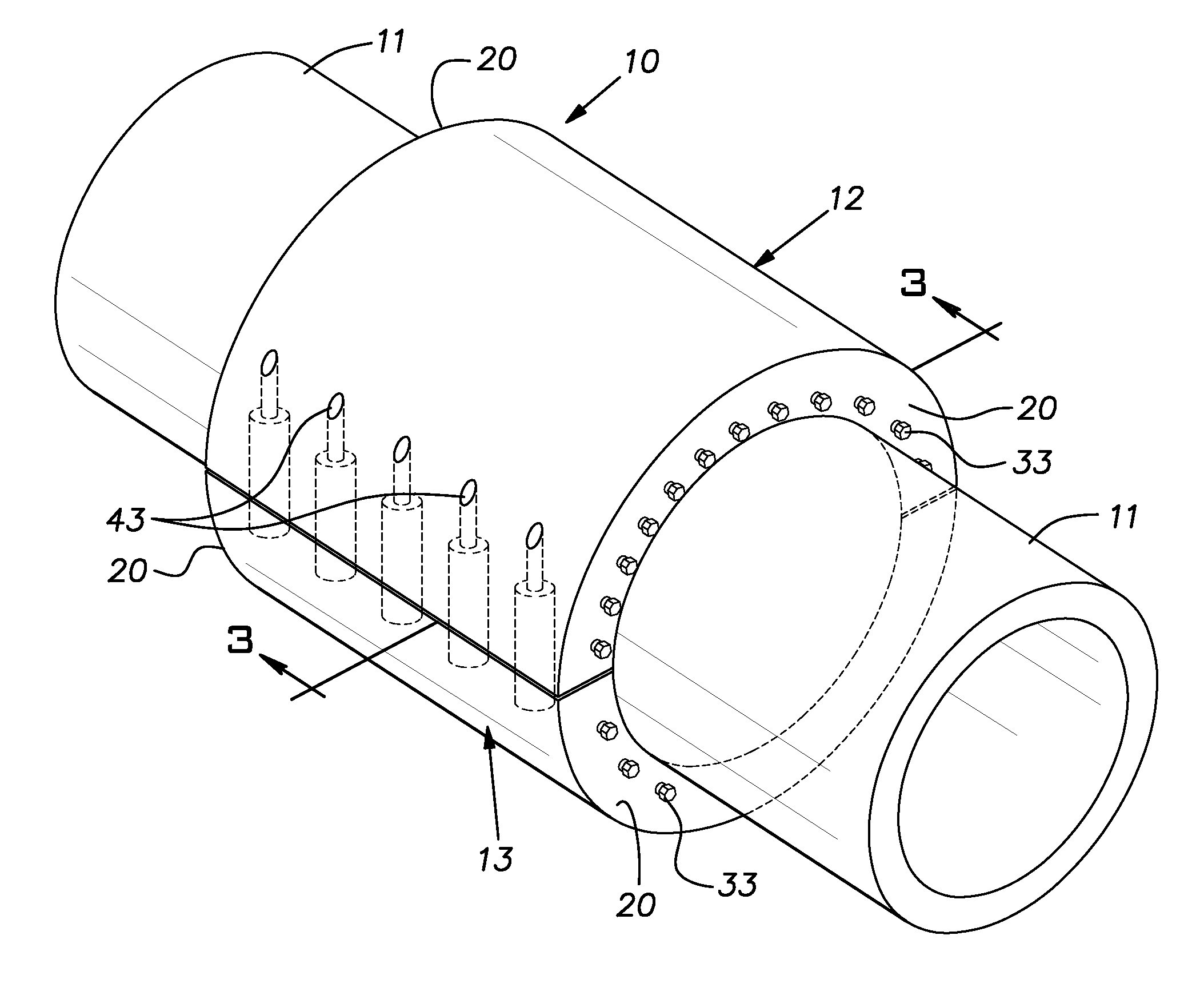
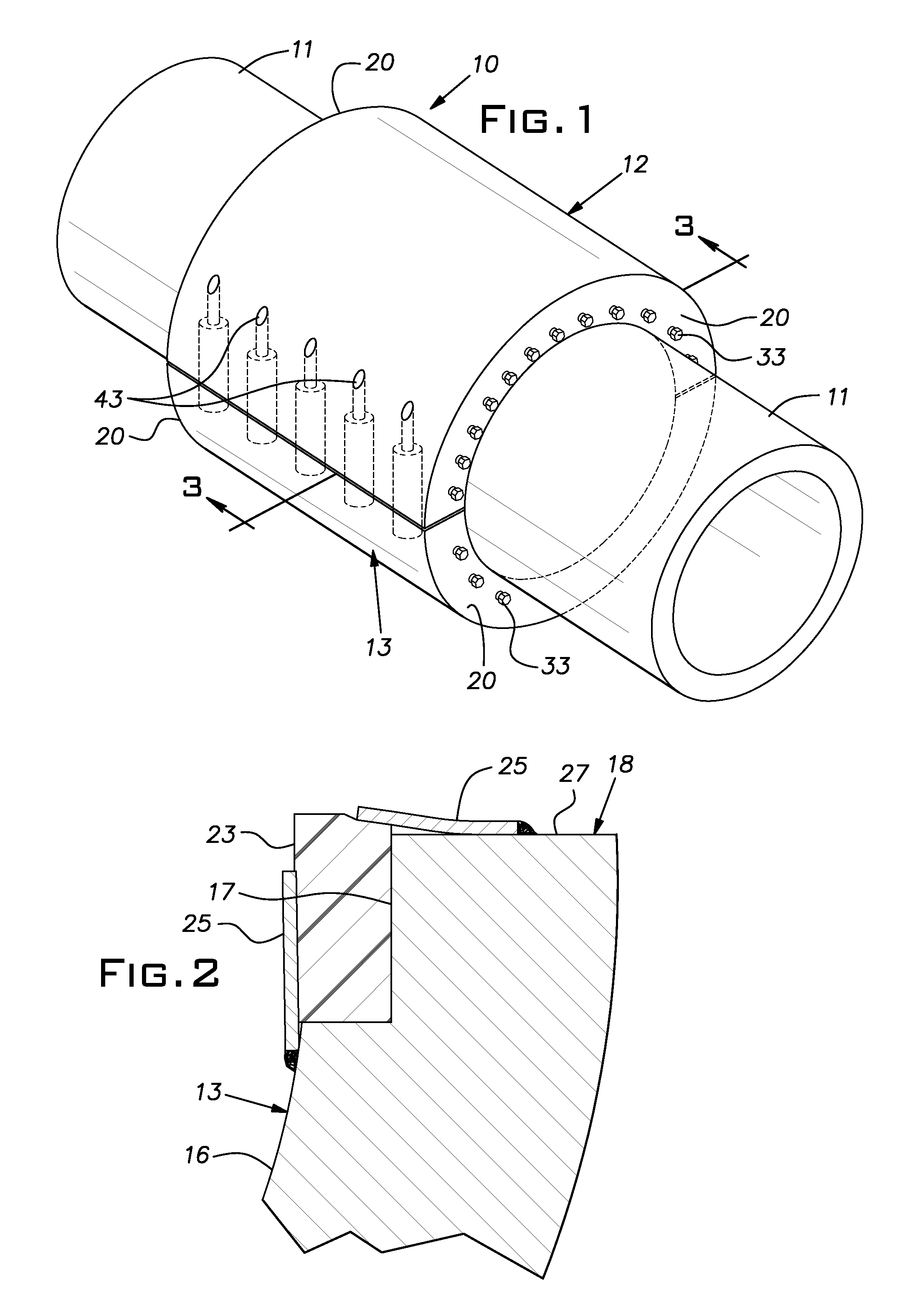
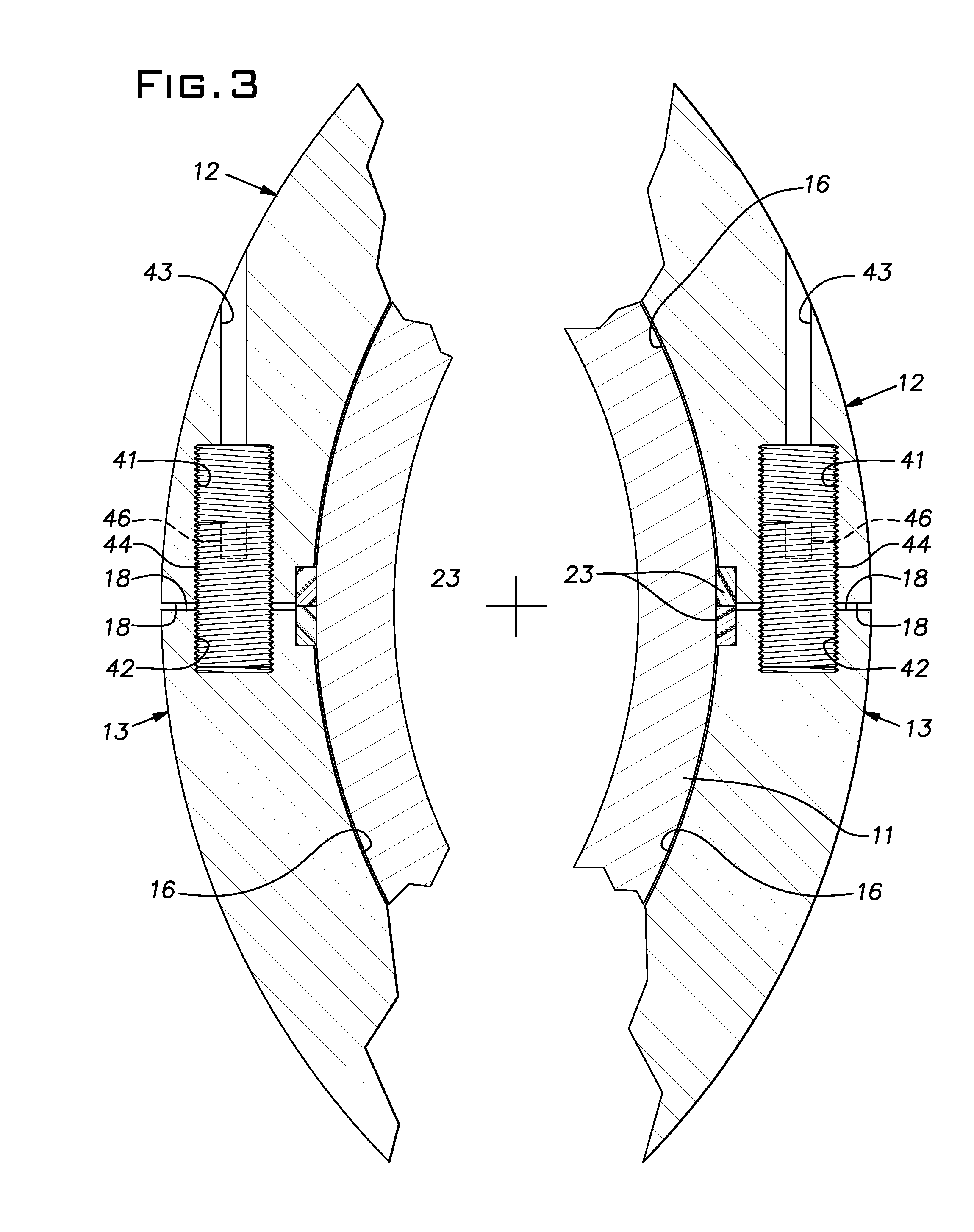
[0014]Referring now to the drawings, there is shown a repair fitting 10 assembled on a pipeline 11 in order to contain leakage from the pipeline due to damage caused by corrosion, accident or other reason. The fitting 10 comprises a hollow cylinder made in two mating half sections or segments 12, 13. The segments 12, 13 in their simplest form are generally uniform in their wall thickness.

[0015]While the segments or half rings 12, 13 can be fabricated from steel tubing, cast of steel, or otherwise made, they commonly will be fabricated from heavy steel plate, typically in a press brake, particularly when large pipe sizes are involved. For example, the segments 12, 13 can be rough formed in a press brake, or with heavy rolls, and then finish machined as required. Typically, the circumferential exterior of the segments 12, 13 can be left as fabricated without machining. The inside cylindrical surfaces 16 of the segments 12, 13 can be machined to assure a clearance fit around the pipeli...


PUM


Abstract

A pipe repair fitting comprising a mating pair of generally semi-circular segments, each formed by an arcuate wall having arcuate ends, the segment walls carrying compressible seals for sealing two pairs of mating arcuate ends of the segments and sealing on the outer periphery of the pipe, at least one threaded hole in each arcuate wall end, a common bolt threaded into each of the threaded holes of each pair of mating arcuate ends and serving to sustain hoop forces in the fitting imposed by fluid leaking out of the pipe and contained by said seals.

Description

BACKGROUND OF THE INVENTION[0001]The invention relates to pipeline repair fittings, particularly of the diametrally split sleeve or ring type.PRIOR ART[0002]Repair of a large pipeline, required because corrosion, collision, other impact, thermal and / or mechanical stress results in a leak, can be made by assembling a split sleeve or ring around the leaking area and then sealing the encircled zone. Conventional split repair fittings, particularly for large diameter pipelines, have often been fabricated from steel plate bent into an arcuate shape configured to fit concentrically over the pipe. Flanges or sidebars, typically cut from heavy steel plate stock, are welded along the axially extending edges of the arcuately bent plates so that the sidebars lie in generally radial directions and complete the arc of a segment comprising one-half of a split fitting. Ultimately, the sidebars of two opposed sleeve or ring segments are bolted together to encircle the pipe being repaired.[0003]The ...

Claims


Application Information

Patent Timeline
Patent Type & Authority Applications(United States)
IPC IPC(8): F16L55/18
CPCF16L55/172
Inventor SMITH, EDWARD B.
Owner PIPE LINE DEVMENT
Why Eureka
Try Eureka