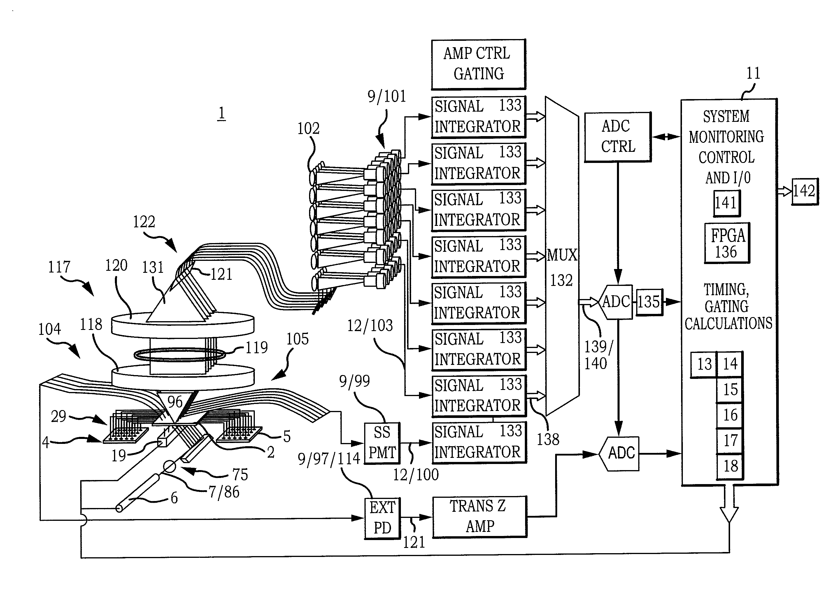
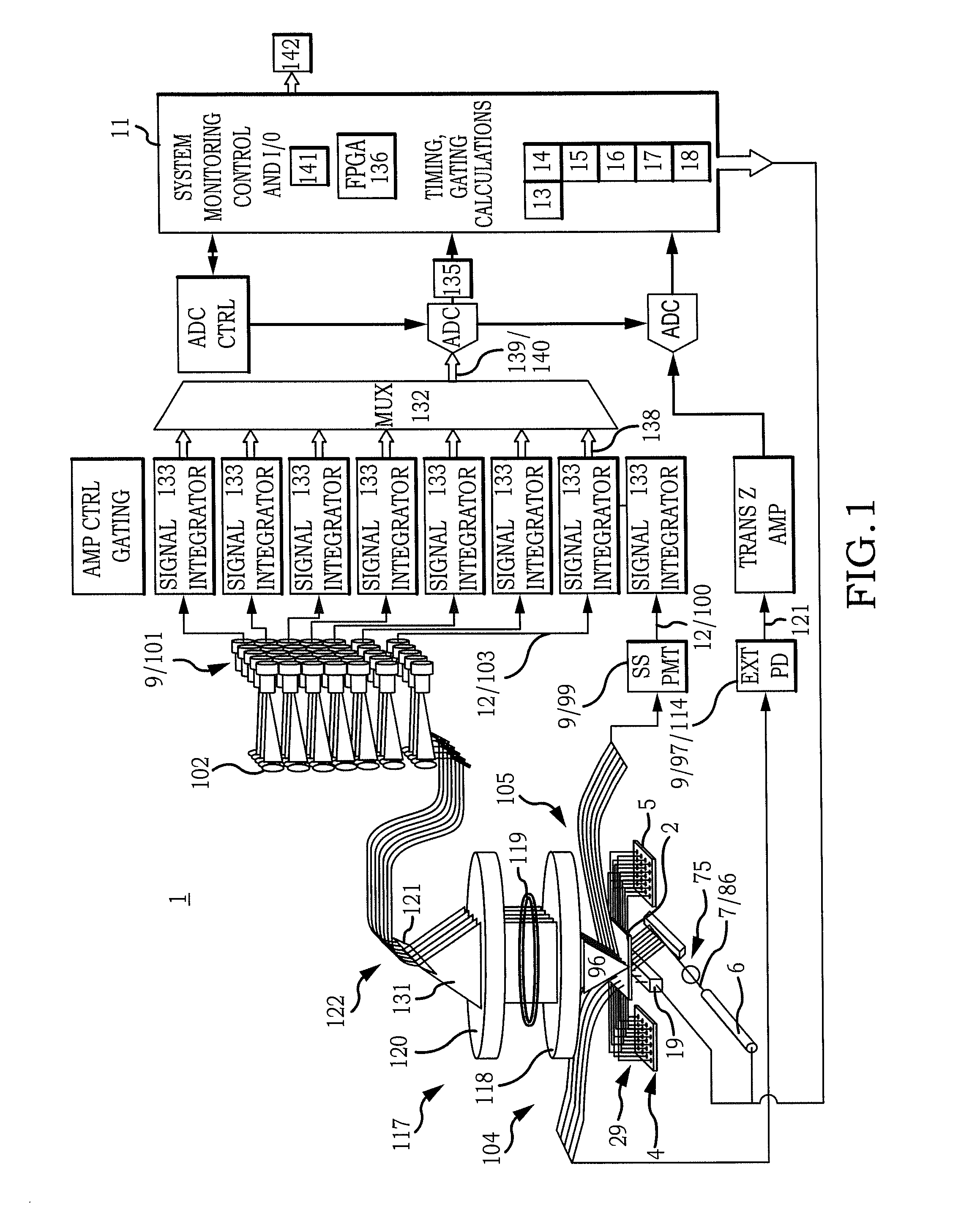
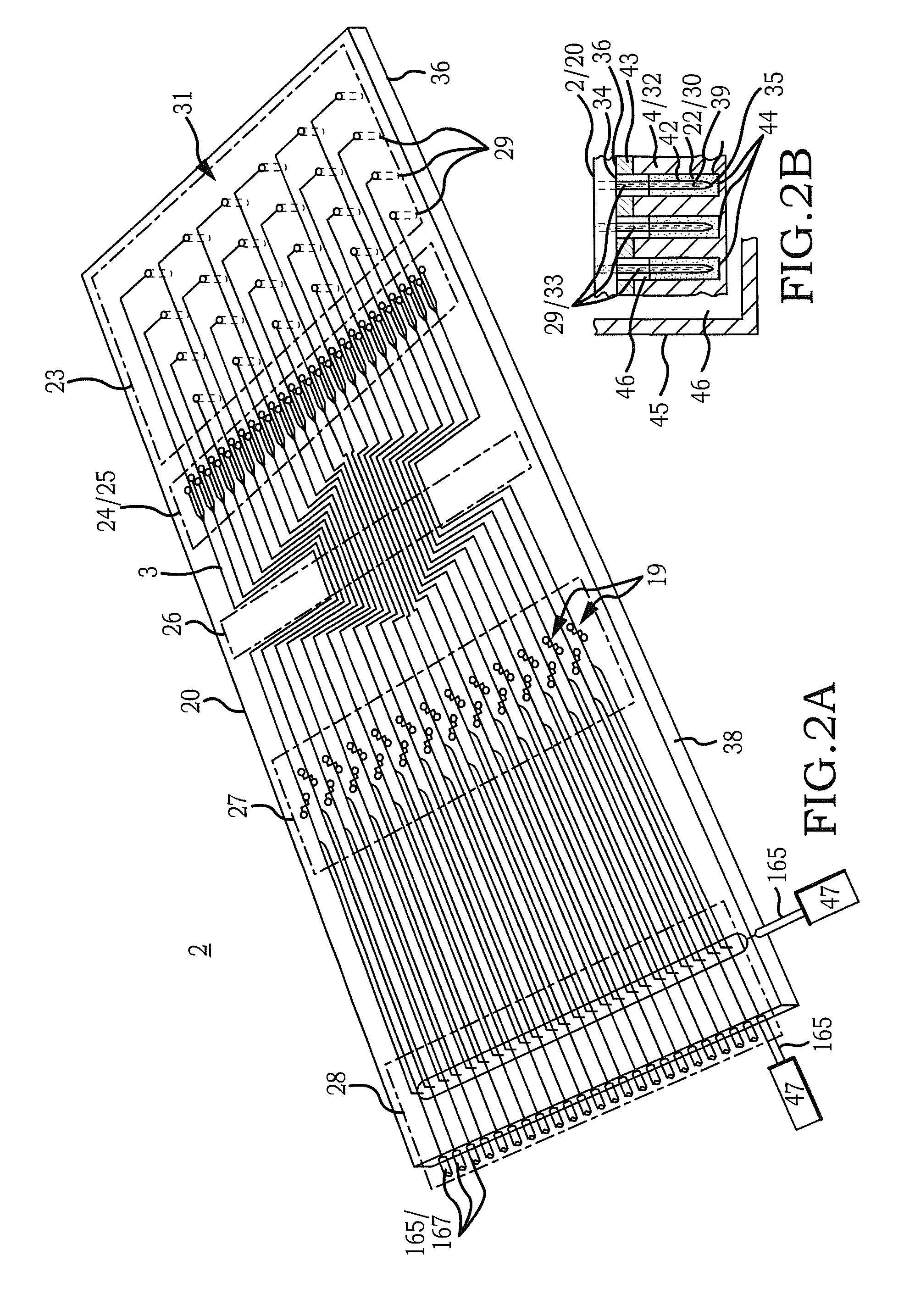
Multiple Flow Channel Particle Analysis System

a particle analysis and flow channel technology, applied in the direction of fluorescence/phosphorescence, instruments, investigating moving fluids/granular solids, etc., can solve the problems of inability to achieve detection or computer system during a period of time, requiring a flow cell of substantially greater constructional and operational complexity, and not being able to achieve the effect of utilizing a conventional unitary flow cytometry system

Active Publication Date: 2012-12-06
CYTONOMEST
View PDF2 Cites 108 Cited by
  • Summary
  • Abstract
  • Description
  • Claims
  • Application Information

AI Technical Summary

Benefits of technology

[0008]Accordingly, a broad object of the invention can be to provide embodiments of a microfluidic multiple flow channel particle analysis system which allows particles from a plurality of particle sources to be independently and simultaneously entrained in a corresponding plurality of fluid streams for analysis and sorting into particle subpopulations based upon one or more particle characteristics.
[0010]Another broad object of the invention can be to provide embodiments which allow unlike particles with different particle characteristics from a plurality of different particle sources to be independently and simultaneously entrained in a corresponding plurality of fluid streams for independent and concurrent analysis and sorting into particle subpopulations based upon one or more particle characteristics.

Problems solved by technology

Because conventional flow cytometers produce only a single fluid stream, the number of particles which can pass through single file through the flow cytometer to be interrogated by the beam of light and associated optical system, detection or computer system can be limited during a period of time.
This approach requires a flow cell of substantially greater constructional and operational complexity than if sufficient centration, alignment and spacing of particles could be achieved within a single fluid stream without utilizing sheath fluid.
This does not appear to have been achieved utilizing a conventional unitary flow cytometry system.

Method used


Image

  • Multiple Flow Channel Particle Analysis System
  • Multiple Flow Channel Particle Analysis System
  • Multiple Flow Channel Particle Analysis System

Examples


example 1

Sorting of Live CD3 Positive T-Cells

[0121]The simultaneous analysis of live CD3 positive human lymphocytes in eight separate channels of a microfluidic chip was performed for the purpose of down stream sorting of mouse PE-conjugated anti-human CD3 labeled human lymphocytes from unlabeled cells, and waste particles.

[0122]A cell mixture containing human lymphocytes and monocytes were purchased from AllCells, 5858 Horton Street, Suite 360, Emeryville, Calif. 94608 (“test cells”). The test cells (5×10⁸ cells per tube) having 95% viability were pelleted by centrifugation, the supernatant decanted and re-suspended in 500 μL phosphate buffered saline (800 g NaCl, 20 g KCl, 144 g Na2HPO4 and 24 g KH2PO4 in 8 L of distilled water), 0.5% bovine serum albumin, and 2 mM ethylene-diamine-tetra-acetic acid (“EDTA”). A 100 μL aliquot of PE-conjugated mouse anti-human CD3 obtained from eBioscience, 10255 Science Center Drive, San Diego, Calif. 92121 was added to the re-suspended test cells and the ...

example 2

Uniformity of Threshold Event Rate Between Flow Channels

[0125]Now referring to FIG. 16, 5 μm particles (PPX-50-50, Sperotech, Inc., 27845 Irma Lee Circle, Unit 101, Lake Forest, Ill. 60045)(also referred to as “particle sample”) were analyzed using a microfluidic chip having 24 flow channels to investigate threshold event and flow rate uniformity across the plurality of flow channels. The particle concentration in the sample fluid was adjusted to 5×10⁶ particles / mL. Pressure was adjusted within the sample source to obtain a mean sample fluid stream flow rate within each of the plurality of flow channels to achieve about 2300 threshold events per second. Substantial uniformity was observed across most of the plurality of flow channels with little variation about the mean apart from three outliers in flow channels 16, 19, and 24.

example 3

Uniformity of Particle Velocity Between Flow Channels

[0126]Now referring to FIG. 17, utilizing the same microfluidic chip as in Example 2, the mean particle velocity was determined for the same particle sample as in Example 2. As shown by the data in FIG. 17, the mean particle velocity was substantially consistent across all 24 flow channels with little variation about the mean.


PUM

PropertyMeasurementUnit
pressureaaaaaaaaaa
pressureaaaaaaaaaa
pressureaaaaaaaaaa

Abstract

A microfluidic multiple channel particle analysis system (1) which allows particles (2) from a plurality of particle sources (3) to be independently simultaneously entrained in a corresponding plurality of fluid streams (4) for analysis and sorting into particle subpopulations (5) based upon one or more particle characteristics (6).

Description

[0001]This application is the United States National Stage of International Patent Corporation Treaty Patent Application No. PCT / US2011 / 000211, filed Feb. 4, 2011, which claims the benefit of U.S. Provisional Patent Application No. 61 / 337,581, filed Feb. 5, 2010, each hereby incorporated by reference herein.I. TECHNICAL FIELD[0002]A microfluidic multiple flow channel particle analysis system which provides a microfluidic chip having a plurality of flow channels each having one or more optical windows which admit an amount of light and a plurality of detectors adapted to generate a corresponding plurality of signals which vary based upon the amount of light passing through or emitted from each of the plurality of flow channels and an analyzer adapted to concurrently analyze a plurality of signals from said plurality of detectors in relation to executable particle analysis processing steps to convert said plurality of signals into data for each of said plurality of flow channels.II. B...

Claims


Application Information

Patent Timeline
Patent Type & Authority Applications(United States)
IPC IPC(8): G01N21/85G01N21/53
CPCG01N15/1012G01N15/1056G01N15/1459G01N15/1484G01N2015/149G01N2015/1075G01N15/1429G01N2015/1402G01N2015/1018G01N21/53G01N21/64
Inventor SHARPE, JOHNATHAN CHARLESMACHADO, EMANUEL TITO MENDESMORAD, BLAIRHULSPAS, RUDOLFPERRAULT, JR., DONALD FRANCIS
Owner CYTONOMEST
Why Eureka
Try Eureka