
Electronic candle

a technology of electronic candles and illuminator wicks, which is applied in the field of candles, can solve the problems of poor effect of illuminator positioned on the electronic wicks, hidden safety troubles, and low cost of ignition-type candles in the prior art, and achieves good effect, reasonable structure, and safety in use.

Inactive Publication Date: 2012-12-06
SHANGHAI Q MALL
View PDF2 Cites 5 Cited by
  • Summary
  • Abstract
  • Description
  • Claims
  • Application Information

AI Technical Summary

Benefits of technology

The present invention provides a safe and aesthetically pleasing electronic candle that overcomes the technical shortcomings of prior art. The electronic candle has a body with a cavity inside, which is equipped with an illuminator and an electronic device controlling the illuminator. The illuminator is connected to a light conductor that extends to the surface of the body through the cavity top to form a section of light-conducting wick. The light conductor is an optical fiber which is good in the light conducting effect. The illuminator is an LED flashlight, flashing the illuminator, transmitting the light for the light conductor in a true flashing effect just as the candle is burnt. The light conducting wick is provided with a light-blocking body at a bottom section, allowing a truer effect of simulative electronic candle just as the wick bottom does not illuminate or burnt black. The illuminator and light conductor are covered with a fixing tube or a transparent lampshade to fasten the bottom of the light conductor and the top of the illuminator in excluding the displacement between the illuminator and light conductor against that the light from the illuminator fails to radiate through the light conductor. The electronic candle can be made with a wax or plastic body, or a body with wax liquid or wax in a glass or transparent container or candle-shaped illuminator. The invention achieves illuminating the body and wick without an additional power supply, thus saving the energy.

Problems solved by technology

The ignition-typed candle in the prior art is cheap in the cost, but with hidden safety troubles.
There are pluralities of commercial electronic candles, wherein most adopt plastic bodies, and a few adopt the wax candle bodies with the illuminator positioned on the electronic wick in a poor effect.
In the foregoing arrangement, the electronic candle is lit merely at the wick, does not illuminate at the body, thus failed to better present the engraved style and shape with lights, especially, even failed to exhibit the aesthetic look of body with sparks in the darkness.

Method used


Image

  • Electronic candle
  • Electronic candle

Examples


embodiment 1

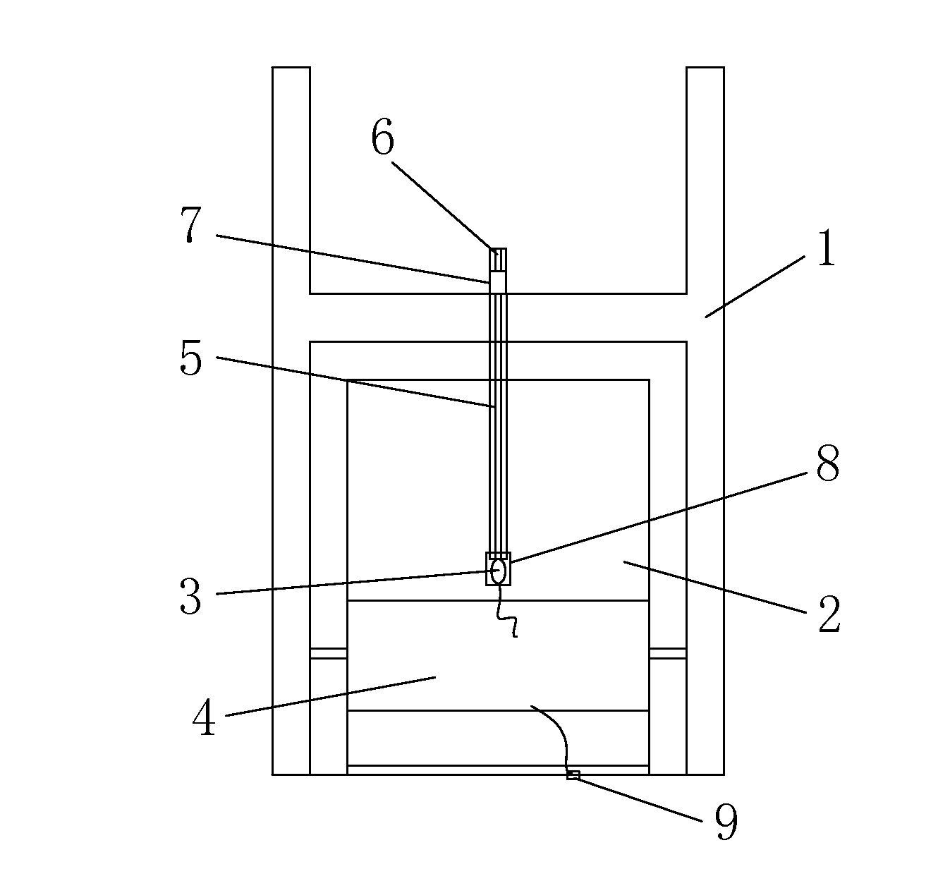
[0015]An electronic candle, consisting of a plastic body 1 which is internally provided with a cavity 2 as illustrated in FIG. 1. The said cavity 2 is mounted an illuminator 3 and an electronic device 4 controlling the illuminator 3, the said illuminator 3 is an LED flashlight, the said body 1 is provided with a driver 9 of the electronic control device 4 at the bottom, the said illuminator 3 is connected with a light conductor 5, the said illuminator 3 and light conductor 5 are covered with a fixing tube 8 at a contact portion, the said light conductor 5 extends to the surface on the said body 1 through the said cavity 2 top to form the section of a light conducting wick 6, the light conducting wick 6 wrapped into a black light-blocking wick 7 with a segment of black plastic sheet at lower section.

embodiment 2

[0016]An electronic candle, consisting of a wax body 1 which is internally provided with a cavity 2 as illustrated in FIG. 1, the said cavity 2 is mounted an illuminator 3 and an electronic device 4 controlling the illuminator 3, the said illuminator 3 is an LED flashlight, the said body 1 is provided with a driver 9 of an electronic control device 4 at the bottom, the said illuminator 3 is connected with an optical fiber conductor 5, the said illuminator 3 and optical fiber conductor 5 are covered with a fixing tube 8 at a contact portion, the said optical fiber conductor 5 extends to the surface on the said body 1 through the said cavity 2 top to form the section of an optical fiber wick 6, the optical fiber wick 6 wrapped into a black light-blocking wick 7 with the segment of black plastic sheet at the lower section.

embodiment 3

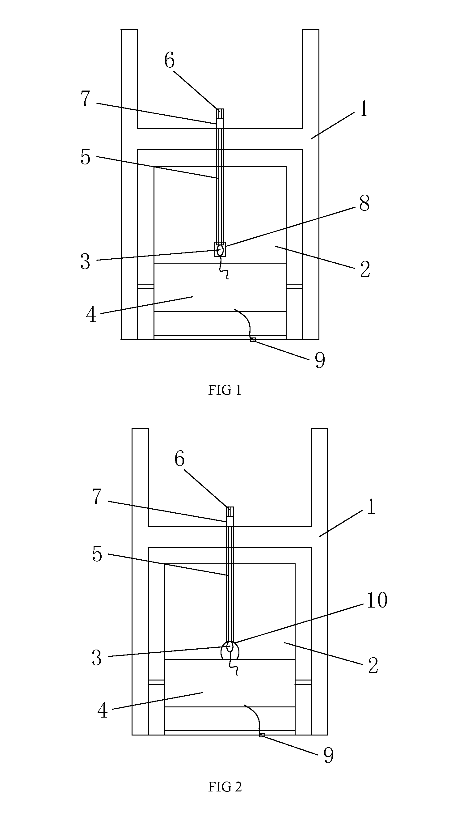
[0017]An electronic candle, consisting of a wax body 1 which is internally provided with a cavity 2 as illustrated in FIG. 2, the said cavity 2 is mounted an illuminator 3 and an electronic device 4 controlling the illuminator 3, the said illuminator 3 is an LED flashlight, the said body 1 is provided with a driver 9 of an electronic control device 4 at the bottom, the said illuminator 3 is connected with an optical fiber conductor 5, the said illuminator 3 is provided with a transparent lampshade 10 which is connected to an optical fiber conductor 5 on the top, the said optical fiber conductor 5 extends to the surface on the said body 1 through the said cavity 2 top to form the section of an optical fiber wick 6, the optical fiber wick 6 wrapped into a black light-blocking wick 7 with the segment of black plastic sheet at the lower section.


PUM


Abstract

The present invention discloses an electronic candle, consisting of a body which is internally provided with a cavity. The said cavity is internally mounted an illuminator and an electronic device controlling the illuminator. The said illuminator is connected to a light conductor which extends to the surface of the body through the cavity top to form the section of a light-conducting wick. The invention has advantages of reasonable structure, safe application, good effect and aesthetic look of body by sputtering away lights.

Description

FIELD OF THE INVENTION[0001]The present invention relates to a candle, particularly to an illuminant electronic candle.BACKGROUND OF THE INVENTION[0002]The ignition-typed candle in the prior art is cheap in the cost, but with hidden safety troubles. There are pluralities of commercial electronic candles, wherein most adopt plastic bodies, and a few adopt the wax candle bodies with the illuminator positioned on the electronic wick in a poor effect. In the foregoing arrangement, the electronic candle is lit merely at the wick, does not illuminate at the body, thus failed to better present the engraved style and shape with lights, especially, even failed to exhibit the aesthetic look of body with sparks in the darkness.SUMMARY OF THE INVENTION[0003]Object of the present invention: The present invention is to settle the technical shortcoming in the prior art, to provide a safe true aesthetic electronic candle.[0004]The technical schemes in the invention: an electronic candle, consisting...

Claims


Application Information

Patent Timeline
Patent Type & Authority Applications(United States)
IPC IPC(8): F21V35/00
CPCF21Y2101/02F21S6/001F21Y2115/10
Inventor DING, YINGQI
Owner SHANGHAI Q MALL
Learn More