
Method, base station, and terminal for generating reference signal

a reference signal and base station technology, applied in the field of communication technologies, can solve problems such as interference in the reception of the base station, and achieve the effect of good orthogonality and accurate demodulation of signals of the two cells

Active Publication Date: 2012-12-06
HUAWEI TECH CO LTD
View PDF6 Cites 28 Cited by
  • Summary
  • Abstract
  • Description
  • Claims
  • Application Information

AI Technical Summary

Benefits of technology

[0006]Embodiments of the present invention provide a method, base station, and terminal for generating a reference signal, so that reference signals sent by UEs of multiple cells have a same hopping rule, thus ensuring good orthogonality between the reference signals sent by the multiple UEs.
[0019]In the technical solutions, with the method, base station, and terminal for generating a reference signal which are provided in the embodiments of the present invention, the UE belonging to the serving cell and the UE belonging to the coordinated cell use a same cyclic shift hopping rule, so that good orthogonality is ensured between the reference signal of the UE belonging to the serving cell and the reference signal of the UE belonging to the coordinated cell which are received in the coordinated cell, so that the coordinated cell demodulates signals of the two cells more accurately, and thereby, the signal transmission performance of the UEs is enhanced.

Problems solved by technology

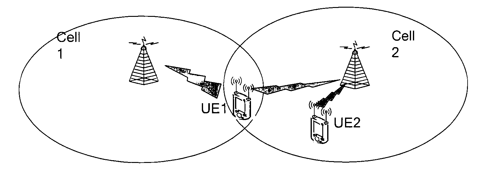
In this way, the base station can receive signals of multiple UEs, and in this case, signals sent by the UEs of other cells cause interference in the reception of the base station.

Method used


Image

  • Method, base station, and terminal for generating reference signal
  • Method, base station, and terminal for generating reference signal
  • Method, base station, and terminal for generating reference signal

Examples


Embodiment Construction

[0029]To make those skilled in the art better understand technical solutions of embodiments of the present invention, the embodiments of the present invention are illustrated in detail with reference to accompanying drawings and implementation manner.

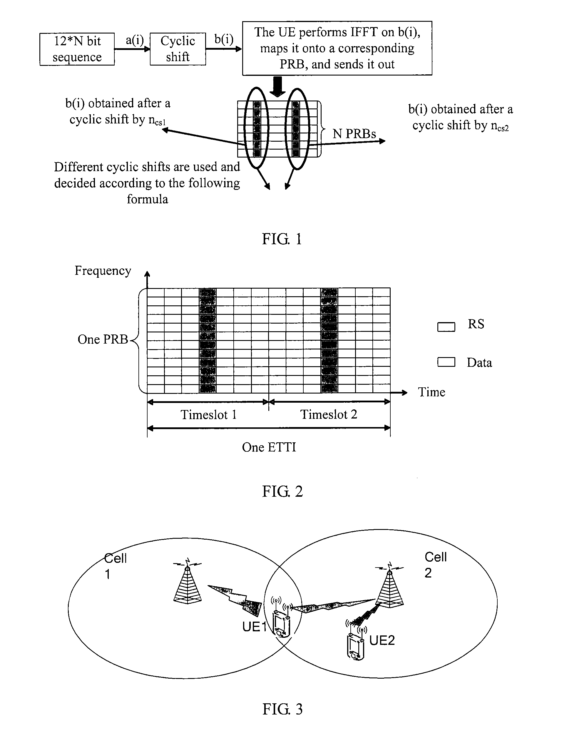
[0030]As shown in FIG. 1 is a schematic diagram of a method for generating an RS by a UE. The UE receives signaling of an evolved Node B (eNB, Evolved Node B), where the signaling includes physical resource blocks (PRBs, physical resource blocks) which are assumed to be 2 PRBs and allocated by the eNB to the UE, and CS information allocated to the UE; the UE generates a root sequence a(i) with the length being 24 (specifically, 12*2, where each PRB includes 12 subcarriers of one transmission time interval (TTI, Transmission Time Interval); in uplink transmission, the reference signal RS is placed in one middle symbol of each timeslot and a schematic structural diagram of the TTI is as shown in FIG. 2); the UE performs a cyclic shift on ...


PUM


Abstract

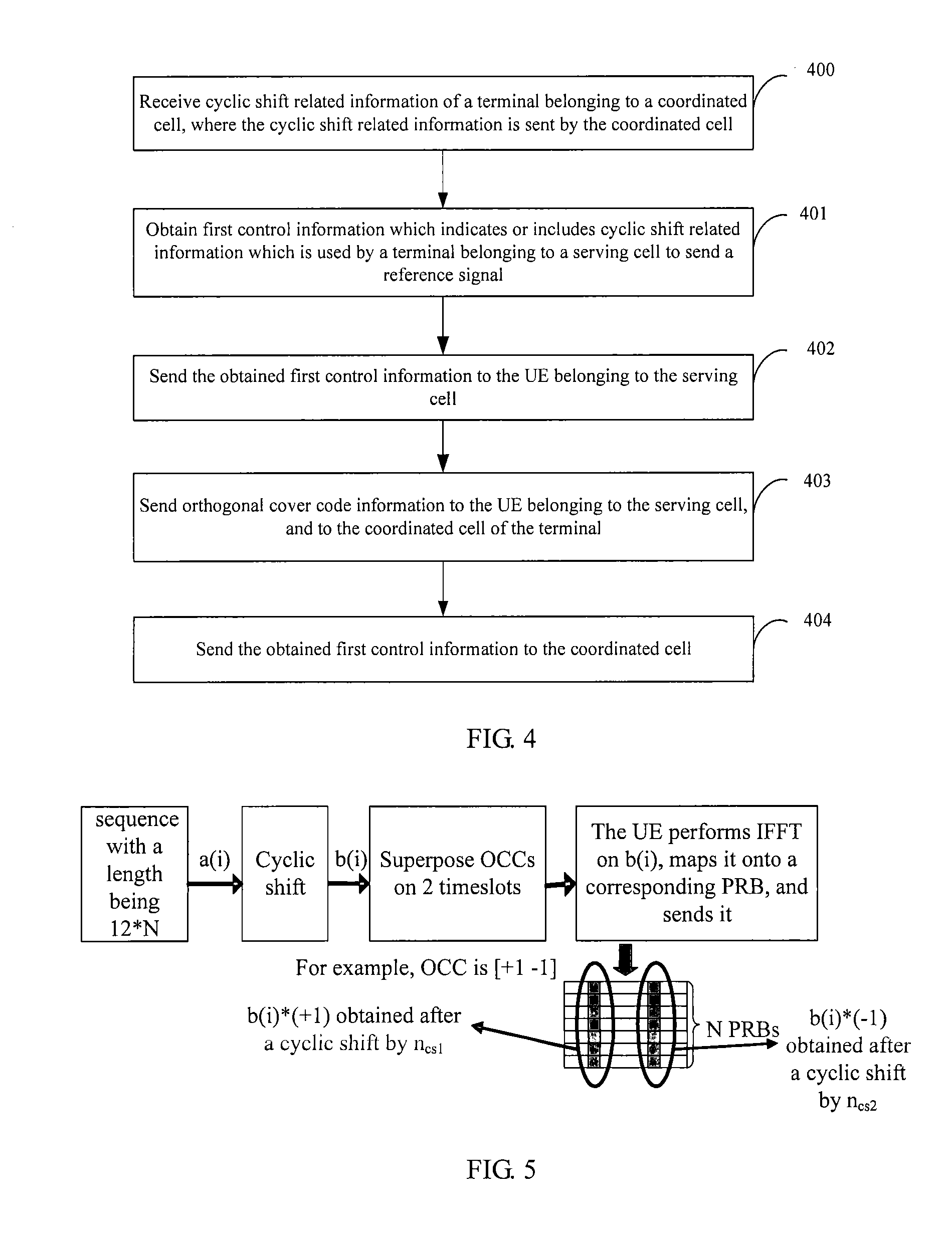
The present invention relates to a method for generating a reference signal, including: obtaining first control information, where the first control information indicates or includes cyclic shift related information which is used by a terminal belonging to a serving cell to send a reference signal; and sending the first control information to the terminal belonging to the serving cell, so that the terminal belonging to the serving cell generates the reference signal according to the cyclic shift related information which is indicated or included by the first control information and used by the terminal to send the reference signal, where a variation rule of a cyclic shift which the terminal belonging to the serving cell uses to generate the reference signal is the same as that of a cyclic shift which a terminal belonging to a coordinated cell uses to generate the reference signal.

Description

CROSS-REFERENCE TO RELATED APPLICATIONS[0001]This application is a continuation of International Application No. PCT / CN2011 / 070906, filed on Feb. 10, 2011, which claims priority to Chinese Patent Application No. 201010113536.6, filed on Feb. 12, 2010, both of which are hereby incorporated by reference in their entireties.FIELD OF THE INVENTION[0002]The present invention relates to communication technologies, and in particular, to a method, base station, and terminal for generating a reference signal.BACKGROUND OF THE INVENTION[0003]In a prior art, a user equipment (UE, User Equipment, or “terminal”) sends data and a reference signal (RS, Reference Signal) to a cell receiver, so that the cell receiver estimates channel fading by using the reference signal and uses the estimated channel fading to check the data sent by the UE; a base station may allocate orthogonal RSs to different UEs in one cell. For example, a base station in a long term evolution (LTE, long term evolution) system ...

Claims


Application Information

Patent Timeline
Patent Type & Authority Applications(United States)
IPC IPC(8): H04B1/69
CPCH04L5/0035H04L27/2613H04L5/0053H04L5/0051
Inventor ZHOU, MINGYUWAN, LEIREN, XIAOTAOXIA, YUANWU, ZUOMINLI, QIANG
Owner HUAWEI TECH CO LTD
Learn More